Multi-axis numerical control linkage welding production line and control method thereof
A welding production line and linkage technology, applied in welding equipment, auxiliary welding equipment, welding/cutting auxiliary equipment, etc., can solve problems such as inability to move left and right, difficult to complete overall welding, and need for manual welding, saving labor costs, The effect of optimizing the welding process and workshop process layout and reducing the amount of manual labor
- Summary
- Abstract
- Description
- Claims
- Application Information
AI Technical Summary
Problems solved by technology
Method used
Image
Examples
Embodiment 1
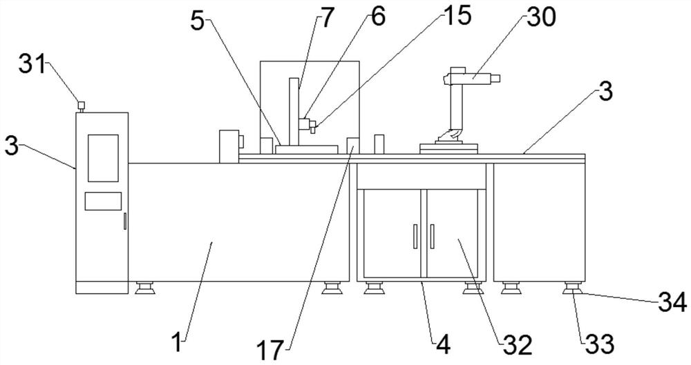
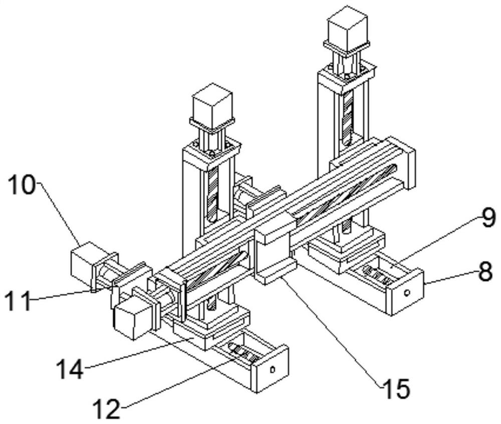
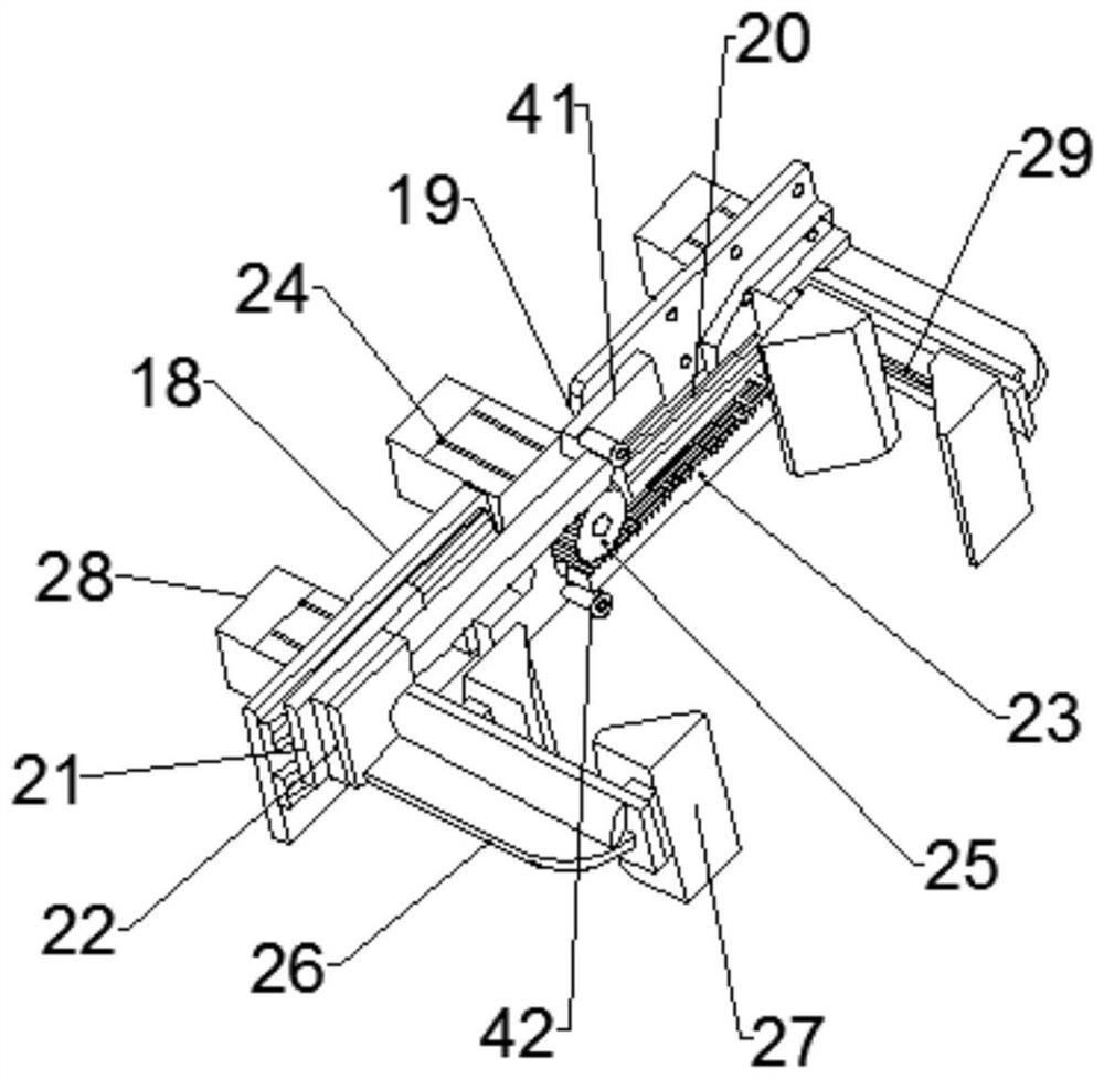
[0031] Such as Figure 1-4As shown, the multi-axis numerical control linkage welding production line and the control method thereof according to the embodiment of the present invention include a support platform 1, a numerical control control box 2 is provided at one end of the support platform 1, and a ball bearing is provided in the middle of the upper end of the support platform 1. screw conveyor line 3, a tool cabinet 4 is provided in the middle of the support table 1, and a Z-axis transmission mechanism 5, an X-axis transmission mechanism 6 and a Y-axis transmission mechanism 7 are provided at one end of the ball screw transmission line 3, so that The Z-axis transmission mechanism 5 is located on both sides of the upper end of the support table 1, the Y-axis transmission mechanism 7 is located in the middle of the upper end of the Z-axis transmission mechanism 5, and is movably connected, and the X-axis transmission mechanism 6 is located on the The middle part of one sid...
Embodiment 2
[0034] Such as Figure 1-4 As shown, one side of the numerical control control box 2 is provided with a heat dissipation grill, and the upper end side of the numerical control control box 2 is provided with a warning light 31 . The front end of the tool cabinet 4 is provided with two doors 32, and one side of the two doors 32 is provided with a handle. The lower ends of the support table 1 are provided with adjustable support legs 33 , and the lower ends of the adjustable support legs 33 are provided with expansion plates 34 , and the expansion plates 34 are welded and fixedly connected with the adjustment support legs 33 .
[0035] Such as Figure 1-4 As shown, the transfer robot arm 30 is composed of joint axis 1 35, joint axis 2 36, joint axis 3 37, joint axis 4 38, joint axis 5 39 and joint axis 6 40. The lower end of the transfer robot arm 30 A fixed base is provided, the upper end of the fixed base is movably connected with the joint shaft 1 35, the upper end of the jo...
Embodiment 3
[0037] In order to facilitate the understanding of the above-mentioned technical solution of the present invention, the flow process of the above-mentioned solution of the present invention will be described in detail below in conjunction with the accompanying drawings, specifically as follows:
[0038] According to an embodiment of the present invention, such as Figure 5 As shown, a multi-axis numerical control linkage welding production line and a control method thereof are also provided.
[0039] The method of the multi-axis numerical control linkage welding production line and its control method comprises the following steps:
[0040] Step S101: Program a plurality of data parameter commands through the numerical control box 2 to obtain predetermined positioning parameters. For the ball screw conveying line 3, the clamping positioning mechanism 17, the Z-axis transmission mechanism 5, the X-axis transmission mechanism 6, The Y-axis transmission mechanism 7 and the handli...
PUM
 Abstract
Description
Claims
Application Information
 - R&D
- Intellectual Property
- Life Sciences
- Materials
- Tech Scout
- Unparalleled Data Quality
- Higher Quality Content
- 60% Fewer Hallucinations
Browse by: Latest US Patents, China's latest patents, Technical Efficacy Thesaurus, Application Domain, Technology Topic, Popular Technical Reports.
© 2025 PatSnap. All rights reserved.Legal|Privacy policy|Modern Slavery Act Transparency Statement|Sitemap|About US| Contact US: help@patsnap.com


