Universal chuck of numerical control tool grinding machine

A tool grinder and chuck technology, which is applied in the field of universal chucks of CNC tool grinders, can solve the problems of easy displacement during processing and difficult clamping of spherical aluminum parts, etc.

Active Publication Date: 2020-12-04
尚特(广州)机器人智能装备有限公司
View PDF12 Cites 5 Cited by
  • Summary
  • Abstract
  • Description
  • Claims
  • Application Information

AI Technical Summary

Problems solved by technology

[0003] Based on the inventors' discovery above, existing methods mainly have the following deficiencies, such as: when the spherical aluminum part is clamped, processed and punched through the clamping teeth of the chuck, the cutting groove of the cutting head is easy to follow the movement of the main shaft. The semicircular cutting diameter is formed by high-speed rotation. When it is embedded in the workpiece laterally, it is easy to shift during processing due to the difficulty of clamping the spherical aluminum part and the plasticity of its own material.

Method used


Image

  • Universal chuck of numerical control tool grinding machine
  • Universal chuck of numerical control tool grinding machine
  • Universal chuck of numerical control tool grinding machine

Examples


Embodiment 1

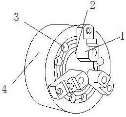
[0025] as attached figure 1 to attach Figure 4 Shown:

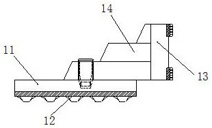
[0026] The present invention provides a universal chuck for a CNC tool grinder, the structure of which includes a clamping tooth 1, a clamping opening 2, a threaded opening 3, and a chuck 4. The locking teeth 1 are inlaid on the inner end surface of the chuck 4 and are evenly distributed. , the clamping port 2 is located at the transverse center of the chuck 4, and the threaded port 3 is uniformly installed on the outer end face of the chuck 4; Trapezoidal block 14, the trapezoidal block 14 is fixedly installed on the upper end surface of the embedded solid bar 11, the inlaid tooth 12 is embedded and fitted directly below the embedded solid bar 11, and the left end surface of the fixed plate 13 is installed on the trapezoidal shaped block by welding. On the right side of the block 14 , the trapezoidal block 14 is inlaid directly above the mosaic teeth 12 .

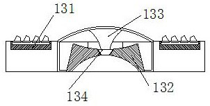
[0027] Wherein, the fixed plate 13 includes a helical tooth ...

Embodiment 2

[0032] as attached Figure 5 to attach Figure 7 As shown: the squeeze ball 34 includes a second air port 341, a rubber ball 342, an arc block 343, and an air valve 344, and the second air port 341 is evenly distributed on the inner surface of the upper end of the rubber ball 342, and the rubber ball 342 is embedded and installed directly above the outer side of the arc-shaped block 343. The arc-shaped block 343 is embedded and installed on the inner upper end surface of the extrusion ball 34. The air valve 344 is symmetrically arranged on the inner surface of the lower end of the extrusion ball 34. The installation position of the air valve 344 is just at the dead angle of the second air port 341 and cannot be overlapped, which can effectively ensure that there is still air on the connecting end faces of the two after extrusion.

[0033] Wherein, the air valve 344 includes an embedding block 441, a seepage mechanism 442, a one-way port 443, and a rubber sheet 444. Located o...


PUM


Abstract

The invention discloses a universal chuck of a numerical control tool grinding machine. The universal chuck structurally comprises clamping teeth, a clamping opening, threaded openings and a chuck body, the clamping teeth are embedded in the end face of the inner side of the chuck body and are evenly distributed, the clamping opening is located in the transverse center of the chuck body, the threaded openings are evenly formed in the end face of the outer side of the chuck body, each clamping tooth comprises an embedding and fixing strip, embedding teeth, a fixed disc and a trapezoidal block,each trapezoid block is fixedly embedded in the upper end face of the corresponding embedding and fixing strip, the embedding teeth are embedded and attached under the corresponding embedding and fixing strip, the end face of the left side of each fixed disc is installed on the right side of the corresponding trapezoid block in a welded mode, each trapezoid block is arranged over the correspondingembedding teeth in an embedded mode, and a machined part is capable of extruding the surface of a closed rubber block to enable the closed rubber block to be sunken inwards. And the closed rubber block is inward extruded while being sunken inwards, so that embedded blocks on the left side and the right side contract inwards after the embedded blocks make contact with a limiting opening, and the inner end face of an air opening is gradually closed while contraction is conducted, so that a closed space is formed in the upper end faces of the fixed discs, and the surface adsorption force and friction force of the spherical machined part are increased.

Description

technical field [0001] The invention belongs to the field of numerical control equipment, and more specifically relates to a universal chuck for a numerical control tool grinder. Background technique [0002] The universal chuck of grinding machine is a kind of equipment used with the hexagonal threaded rod. The hexagonal threaded rod is embedded and rotated, and the three movable calipers installed on the surface of the chuck are driven by the disc gear transmission in the chuck. Shrink to clamp the workpiece. [0003] Based on the inventors' discovery above, existing methods mainly have the following deficiencies, such as: when the spherical aluminum part is clamped, processed and punched through the clamping teeth of the chuck, the cutting groove of the cutting head is easy to follow the movement of the main shaft. Rotating at high speed to form a semicircular cutting diameter, when it is embedded in the workpiece laterally, it is easy to shift during processing due to t...

Claims


Application Information

Patent Timeline
Patent Type & Authority Applications(China)
IPC IPC(8): B24B11/02B24B41/06
CPCB24B11/02B24B41/06
Inventor 卢敏
Owner 尚特(广州)机器人智能装备有限公司
Why Eureka
Try Eureka