Automobile wax and preparation system and preparation method thereof
A technology for preparing systems and car waxes, which is applied in the direction of chemical instruments and methods, polishing compositions, etc., and can solve problems such as stirring internal raw materials
- Summary
- Abstract
- Description
- Claims
- Application Information
AI Technical Summary
Problems solved by technology
Method used
Image

Examples
specific Embodiment approach 1
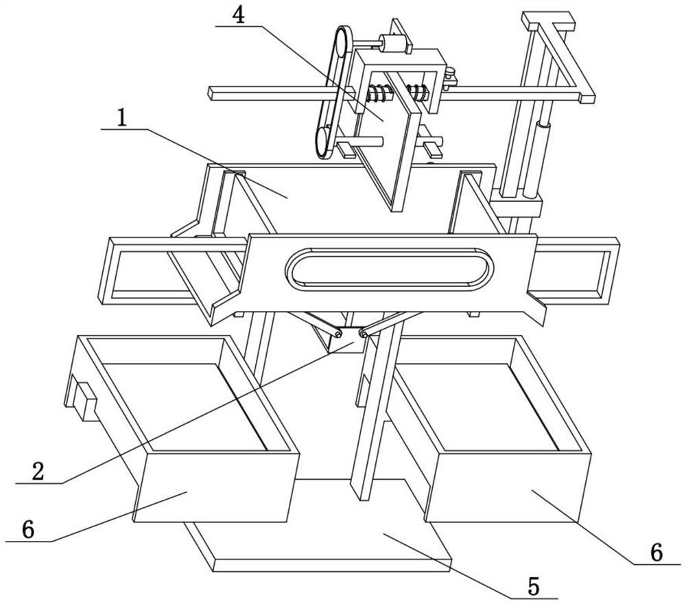
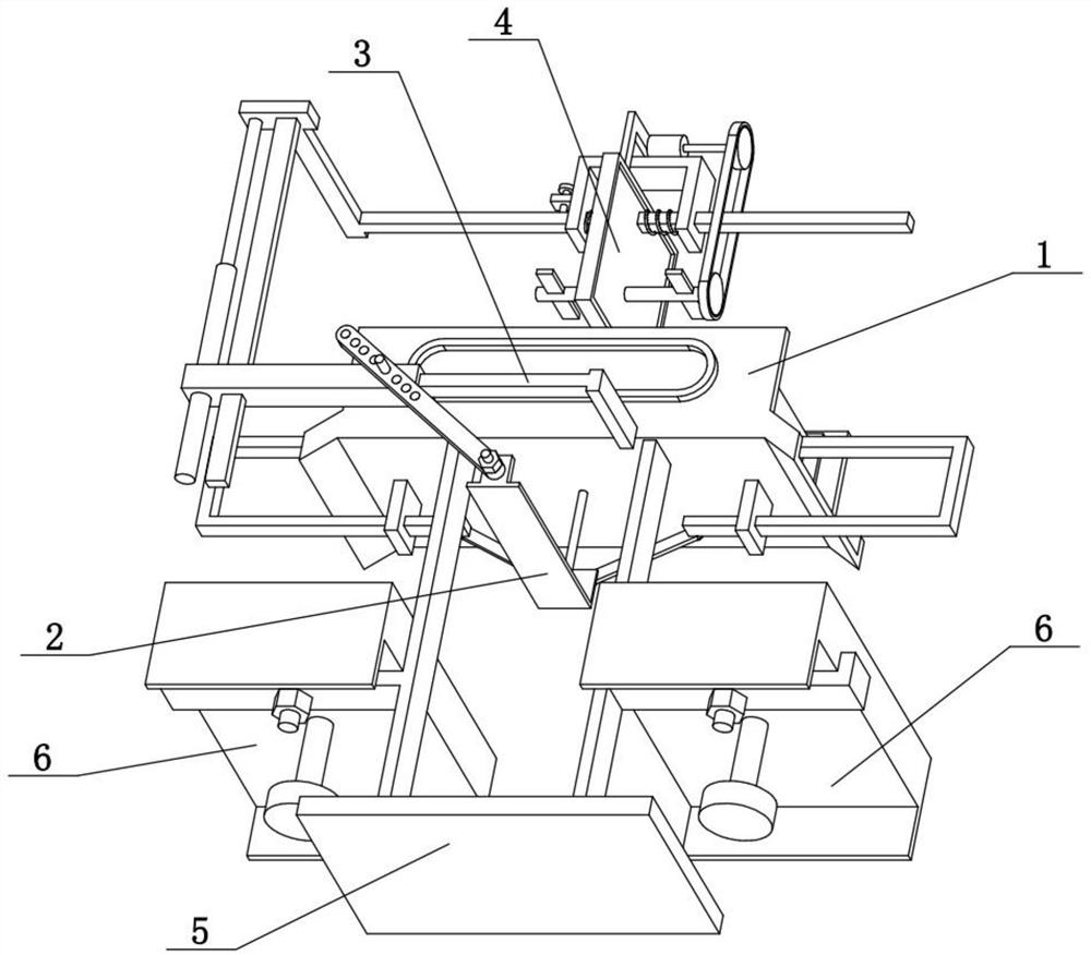
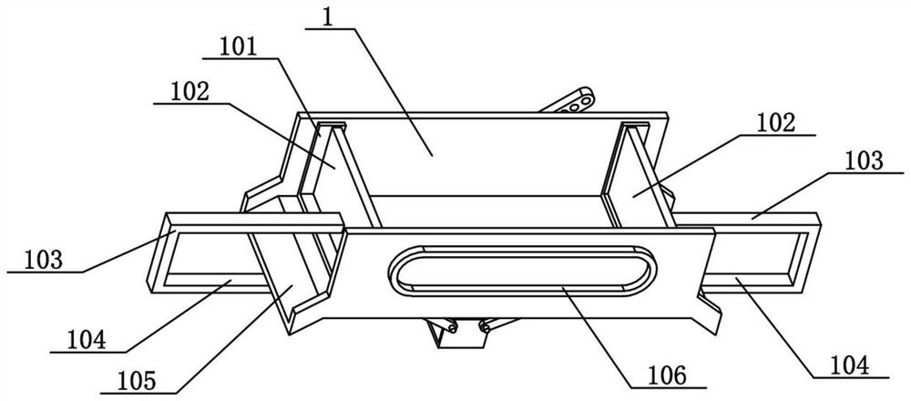
[0034] The following combination Figure 1-9 Explaining the embodiment, the invention relates to the field of automobile wax preparation, in particular to an automobile wax preparation system, which comprises a tank box 1, a sealing strip 101, side plates 102, an L-shaped column 103, a transverse sliding column 104, a guide groove 105 and a convex plate 107. The invention can change the volume of the tank box 1 through the left-right movement of the two side plates 102, stir the internal raw materials while changing the volume, and when the two side plates 102 are separated.
[0035] The left and right sides of the tank box 1 are open, the left and right ends inside the tank box 1 are slidably connected with side plates 102 in the left and right directions, a sealing strip 101 is arranged between the two side plates 102 and the tank box 1, the outer sides of the two side plates 102 are fixedly connected with L-shaped columns 103, the lower parts of the left and right sides of the t...
specific Embodiment approach 2
[0037] The following combination Figure 1-9 Explaining this embodiment, the automobile wax preparation system further comprises an electric heating wire 106, and the front and rear sides of the tank box 1 are provided with electric heating wires 106. The electric heating wire 106 can heat the raw material to prevent the raw material from solidifying.
specific Embodiment approach 3
[0039] The following combination Figure 1-9 Explaining this embodiment, the automobile wax preparation system further comprises a lifting plate 2, an equal-length rod 204 and an electric push rod I205. The front end of the lifting plate 2 is hinged with two equal-length rods 204, and the other ends of the two equal-length rods 204 are hinged with the inner ends of the two transverse sliding columns 104 respectively. The lower central position of the tank box 1 is fixedly connected with the electric push rod I205, and the movable end of the electric push rod I205 is fixedly connected with the upper side of the lifting plate 2. When the electric push rod I205 retracts, it can drive the lifting plate 2 to move up and down. When the lifting plate 2 moves up and down, the two horizontal sliding columns 104 are driven to approach or move away from each other by two equal-length rods 204, and then the two side plates 102 are driven to approach or move away from each other.
PUM
 Abstract
Description
Claims
Application Information
 - R&D
- Intellectual Property
- Life Sciences
- Materials
- Tech Scout
- Unparalleled Data Quality
- Higher Quality Content
- 60% Fewer Hallucinations
Browse by: Latest US Patents, China's latest patents, Technical Efficacy Thesaurus, Application Domain, Technology Topic, Popular Technical Reports.
© 2025 PatSnap. All rights reserved.Legal|Privacy policy|Modern Slavery Act Transparency Statement|Sitemap|About US| Contact US: help@patsnap.com