Building drainage collection system

A technology for building drainage and drainage pipes, used in waterway systems, buildings, drainage structures, etc., can solve the problems of small maintenance space, inability to maintain, and high production costs, reducing the space occupied, preventing odor from overflowing, increasing The effect of the radius of curvature

Active Publication Date: 2020-12-04
KANGTAI PLASTIC SCI & TECH GRP
View PDF10 Cites 4 Cited by
  • Summary
  • Abstract
  • Description
  • Claims
  • Application Information

AI Technical Summary

Problems solved by technology

Although the second-generation building drainage system solves the problem that the leakage of the first-generation building drainage system affects the lower-level residents, when using the second-generation building drainage system, the height of the floor 401 needs to be lowered at the pipe installation site, which still encroaches on the lower-level residents. space, and water accumulation is prone to occur in the cushion layer, making pipeline maintenance difficult and inconvenient for construction
[0005] In addition, in the prior art, horizontal pipe drainage pipes are often laid in the building wall and inspection ports are provided. When the pipes or water seals are blocked, the operator needs to open a special inspection port for inspection in the wall. Obstacles to the field of view, the operator has poor field of vision and small space for inspection during inspection, and the inspection of the horizontal pipe drainage pipe is inconvenient or even impossible
Moreover, the drainage structure of the prior art is complex, the manufacturing process is loaded down with trivial details, and the production cost is high, which is particularly unfavorable for mass production

Method used


Image

  • Building drainage collection system
  • Building drainage collection system
  • Building drainage collection system

Examples


Embodiment 1

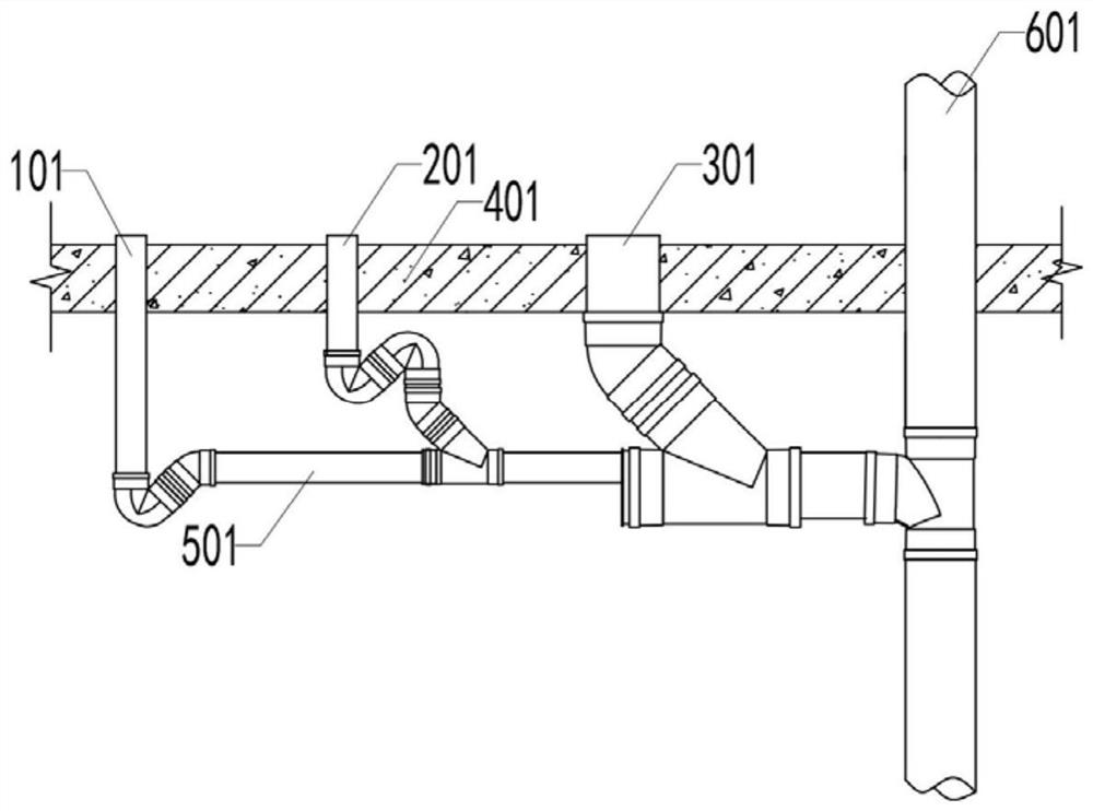
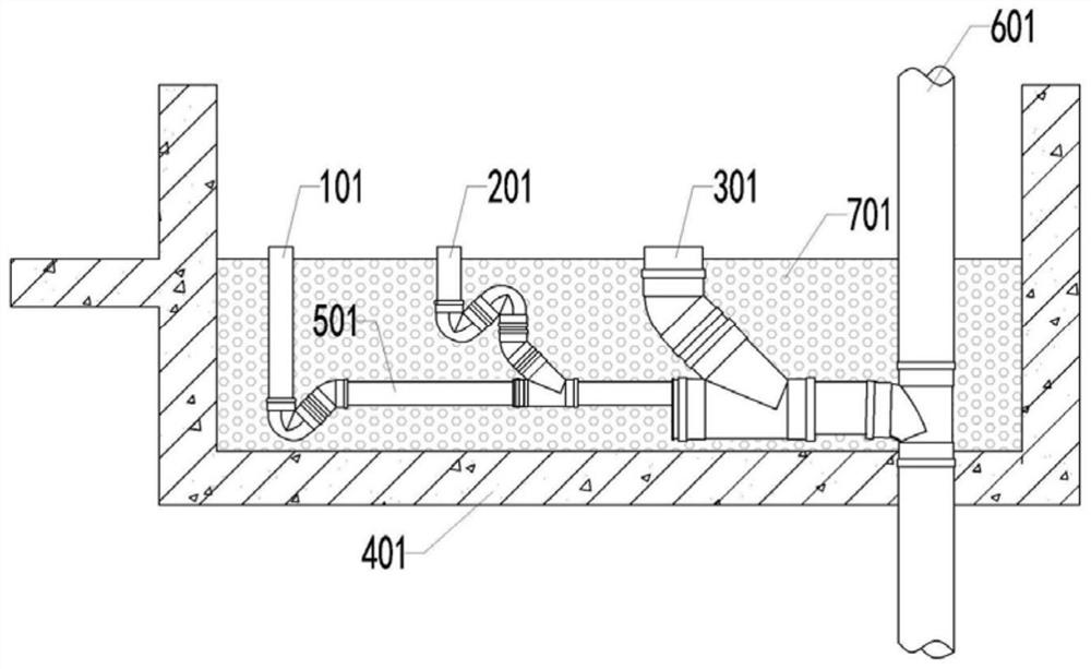
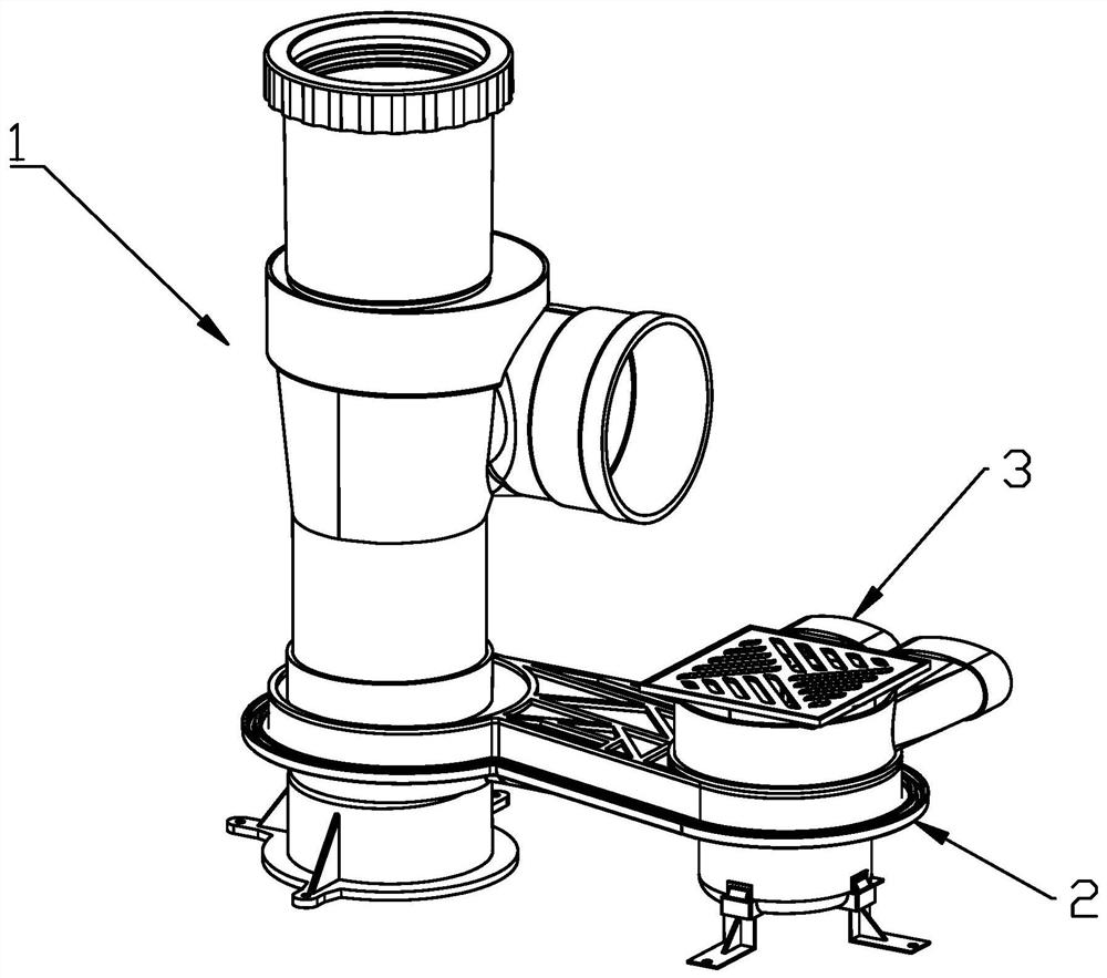
[0075] refer to Figure 3-16 , the present embodiment provides a building drainage collection system, said building drainage collection system is inscribed between the sewage main drainage pipes during actual installation, and communicates with the main sewage drainage pipes up and down. It includes a drain pipe assembly 1, a horizontal pipe drainage assembly 2 communicated with the drain pipe assembly 1, and a water seal assembly 3 communicated with the horizontal pipe drainage assembly 2. In this embodiment, the sewage refers to the water discharged from the toilet, and the waste water refers to the water discharged from the shower, washbasin and the like.

[0076] see Figure 3-Figure 10 The drain pipe assembly 1 includes a first water inlet pipe 11, a second water inlet pipe 12, a first standpipe 13 and a second standpipe 14; the first water inlet pipe 11 is connected to the second water inlet pipe 12 and internally communicated, and The inner edge of the second water in...

Embodiment 2

[0109] see Figure 18-20 , this embodiment only improves the positional relationship between the first filter screen 3223, the opening end 311 of the water storage part 31 and the inner wall of the second assembly part 22 in embodiment 1, and the rest of the structures and connection relationships are not adjusted.

[0110] The first filter screen 3223 is replaced by a check valve 5, the check valve includes a plurality of cover sheets 51, and the cover sheets 51 include a fan-shaped main body 511, and the fan-shaped main body 511 is away from the side of the fan-shaped circle center. The lower part is provided with a gravity block 512;

[0111] A cover plate support frame 52, a positioning bar 521 is arranged on the cover plate support frame 52, and the positioning bar 521 extends downward, and a stopper 522 is provided at the bottom end of the positioning bar 521;

[0112] The cover sheet 51 is rotatably mounted on the cover sheet support frame 52, and the cover sheet suppo...


PUM


Abstract

The invention provides a building drainage collection system. The building drainage collection system comprises a drainage pipe assembly, a transverse pipe drainage assembly communicating with the drainage pipe assembly, and a water seal assembly communicating with the transverse pipe drainage assembly, wherein the interior of the transverse pipe drainage assembly is of a flat cavity structure, and the bottom surface of a cavity of the transverse pipe drainage assembly is obliquely arranged. According to the building drainage collection system, the flat transverse pipe drainage assembly is adopted to be connected with the drainage pipe assembly and the water seal assembly, so that the occupied space is small, and the technical effect of sewage and wastewater drainage can be achieved without lowering a floor slab layer.

Description

technical field [0001] The invention relates to the field of building drainage systems, in particular to a building drainage collection system. Background technique [0002] The development process of building drainage system roughly has the following two stages: [0003] refer to figure 1 , figure 1 The building drainage system shown in is the first-generation building drainage system. The first connecting pipe 101 connected to the floor drain, the second connecting pipe 201 connected to the sink, and the third connecting pipe 301 connected to the toilet are all set through the floor 401 . The waste water in the first connecting pipe 101, the waste water in the second connecting pipe 201 and the sewage in the third connecting pipe 301 pass through the main pipe 501 into the confluence riser 601 to discharge the sewage. Since the first connecting pipe 101, the second connecting pipe 201, and the third connecting pipe 301 are all installed through the floor 401, the first...

Claims


Application Information

Patent Timeline
Patent Type & Authority Applications(China)
IPC IPC(8): E03C1/122E03C1/28E03F5/04E03F5/042E03F5/06
CPCE03C1/122E03C1/1222E03C1/28E03F5/0407E03F5/042E03F5/06Y02A30/60
Inventor 郑术友林云青黄陈磊杨明龙何谦
Owner KANGTAI PLASTIC SCI & TECH GRP
Why Eureka
Try Eureka