
Three-cavity oil tank, oil supply device for engine carbon hydrogen injection system and vehicle

A technology of injection system and oil supply device, which is applied to fuel injection devices, engine components, machines/engines, etc., can solve the problems of high cost, complex structure, waste of resources, etc. Effect

Inactive Publication Date: 2020-12-04
DONGFENG COMML VEHICLE CO LTD
View PDF6 Cites 0 Cited by
  • Summary
  • Abstract
  • Description
  • Claims
  • Application Information

AI Technical Summary

Problems solved by technology

[0004] However, the above scheme has the following disadvantages: complex structure and high cost, and it is necessary to add external heating equipment to heat the fuel in the mailbox
[0005] For vehicles with a hydrocarbon injection system, the hydrocarbon injection system is usually directly connected to the main fuel tank. Since the hydrocarbon injection device is working, it basically uses 0# diesel oil in the main fuel tank. After the hydrocarbon injection device is working, 0 #Diesel oil will remain in the hydrocarbon injection device and the inlet and outlet pipes of the hydrocarbon injection device. When the ambient temperature is low, because the hydrocarbon injection device cannot be heated, 0# diesel will be waxed. When the hydrocarbon injection device needs to inject again , it will not work properly due to waxing of 0# diesel oil
However, if the hydrocarbon injection system is matched with the fuel tank in CN109878328A, resources will be wasted

Method used


Image

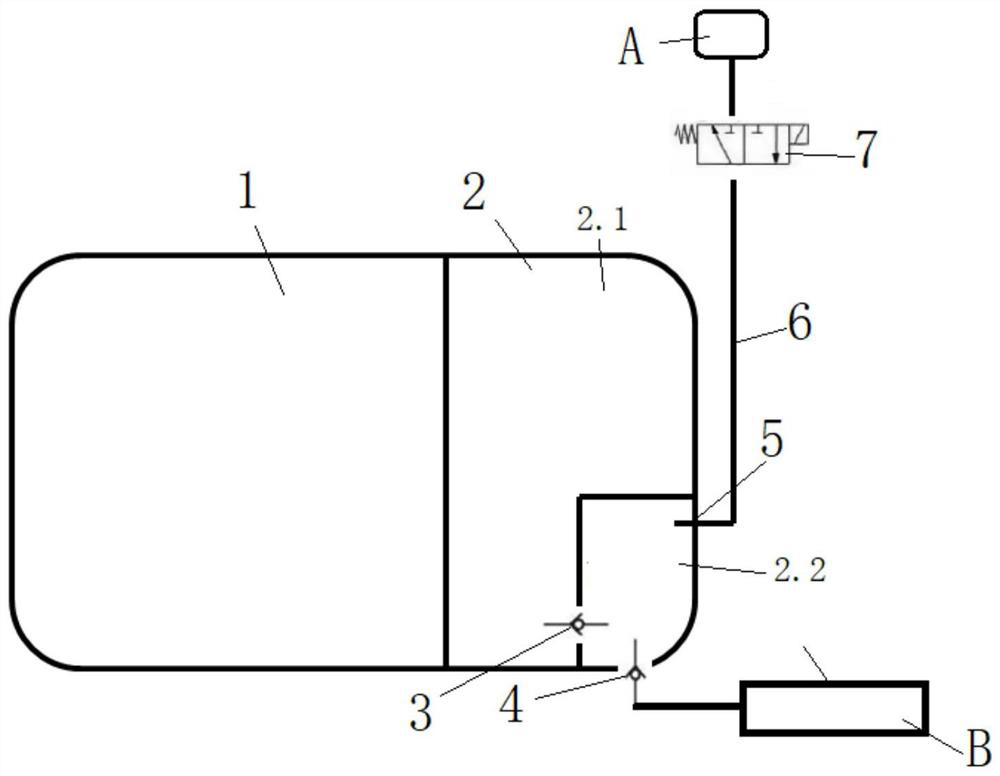
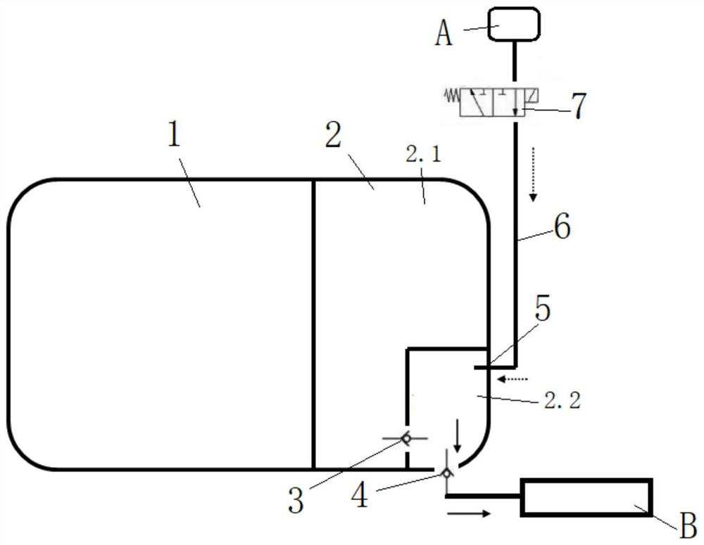
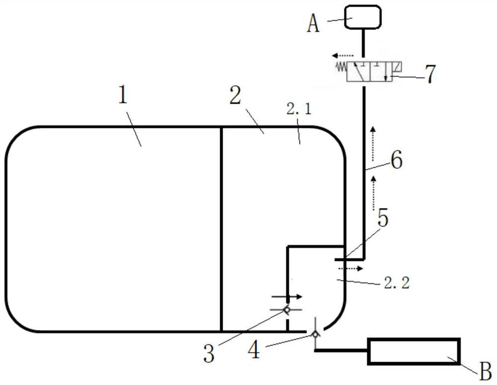
  • Three-cavity oil tank, oil supply device for engine carbon hydrogen injection system and vehicle
  • Three-cavity oil tank, oil supply device for engine carbon hydrogen injection system and vehicle
  • Three-cavity oil tank, oil supply device for engine carbon hydrogen injection system and vehicle

Examples


Embodiment Construction

[0022] The technical solution (including the preferred technical solution) of the present invention will be further described in detail below by way of describing the accompanying drawings and enumerating some optional embodiments of the present invention. Apparently, the described embodiments are only some of the embodiments of the present invention, not all of them. Based on the embodiments of the present invention, all other embodiments obtained by persons of ordinary skill in the art without creative efforts fall within the protection scope of the present invention.

[0023] The invention discloses a three-chamber oil tank, which comprises a box body, the inner cavity of the box body is divided into an airtight main chamber 1 and an airtight sub-chamber 2 by a first partition, and the sub-chamber 2 is separated by a second partition It is an airtight oil storage chamber 2.1 and an airtight oil supply chamber 2.2. The second partition is provided with a first one-way valve ...


PUM


Abstract

The invention discloses a three-cavity oil tank, an oil supply device for an engine carbon hydrogen injection system and a vehicle. The three-cavity oil tank comprises a tank body. An inner cavity ofthe tank body is partitioned into a main cavity and an auxiliary cavity through a first partition plate. The auxiliary cavity is partitioned into an oil storing cavity and an oil supply cavity througha second partition plate. The second partition plate is provided with a first one-way valve used for inputting fuel oil in the oil storing cavity into the oil supply cavity. The tank body is providedwith a second one-way valve used for outputting the fuel oil in the oil supply cavity to external equipment, and a loading opening communicating with the oil supply cavity. According to the tank, under the circumstance of not additionally arranging the external heating equipment, low-temperature fuel oil in the oil tank is directly utilized for supplying oil to a carbon hydrogen injection device,and therefore the carbon hydrogen injection device can work normally under the circumstance of low environment temperature.

Description

technical field [0001] The invention discloses a fuel tank, a fuel supply device for a hydrocarbon injection system and a vehicle, and belongs to the technical field of fuel supply devices for a hydrocarbon injection system, and specifically discloses a three-cavity fuel tank, a fuel supply device for an engine hydrocarbon injection system and vehicle. Background technique [0002] The fuel tank is a device for storing fuel oil in the car. Currently, the fuel tank equipped on the car is a single-chamber fuel tank. In the northern region, the average temperature in winter is around minus 10-30 degrees Celsius. Ordinary fuel tanks cannot meet the requirements for use. You can often see When some vehicles use low-grade diesel, the diesel is frozen and waxed, which makes it difficult to atomize after entering the engine, which seriously reduces the utilization rate of diesel. When using high-grade diesel, it increases the cost of use. The device that uses fuel oil to heat zero-...

Claims


Application Information

Patent Timeline
Patent Type & Authority Applications(China)
IPC IPC(8): F02M37/00F02M61/16F02M63/00
CPCF02M37/00F02M37/0023F02M37/0088F02M61/16F02M63/00
Inventor 严波林浩樊有林曹翰卿殷勇李建峰李海言
Owner DONGFENG COMML VEHICLE CO LTD
Learn More