
Bidirectional electromagnetic valve

A two-way solenoid valve and valve body technology, applied in the field of solenoid valves, can solve problems such as unreliable work, medium leakage, and increased production costs, and achieve the effects of increasing the effective working surface area, ensuring reliability, and improving sealing

Pending Publication Date: 2020-12-04
吴奇勋
View PDF1 Cites 3 Cited by
  • Summary
  • Abstract
  • Description
  • Claims
  • Application Information

AI Technical Summary

Problems solved by technology

[0002] Two-way solenoid valves on the market generally have two valve discs, so the processing and assembly conditions of the two valve discs are extremely demanding, otherwise it is not conducive to the sealing of the medium, making the structure of the solenoid valve more complicated and increasing the production cost
In addition, if one of the two valve discs is damaged, the leakage of the medium will occur, resulting in unreliable work.
[0003] There are also some technical solutions in the prior art, such as the Chinese patent with the application number CN201821343709.1, which includes electromagnetic components and valve body components. The above-mentioned electromagnetic valve can effectively prevent the backflow of the medium in the process of controlling the use of the fluid, but There is also the following problem. When controlling the flow, the solution can only adjust the diversion channel through the valve body in one direction, and cannot perform dual-channel adjustment and control according to the flow direction of the liquid. In addition, the solenoid valve is used for a long time. The internal sealing plug is prone to wear and aging, which will reduce the sealing effect of the solenoid valve, cause leakage, and reduce the reliability of the solenoid valve when it is working.

Method used


Image

  • Bidirectional electromagnetic valve
  • Bidirectional electromagnetic valve
  • Bidirectional electromagnetic valve

Examples


Embodiment approach

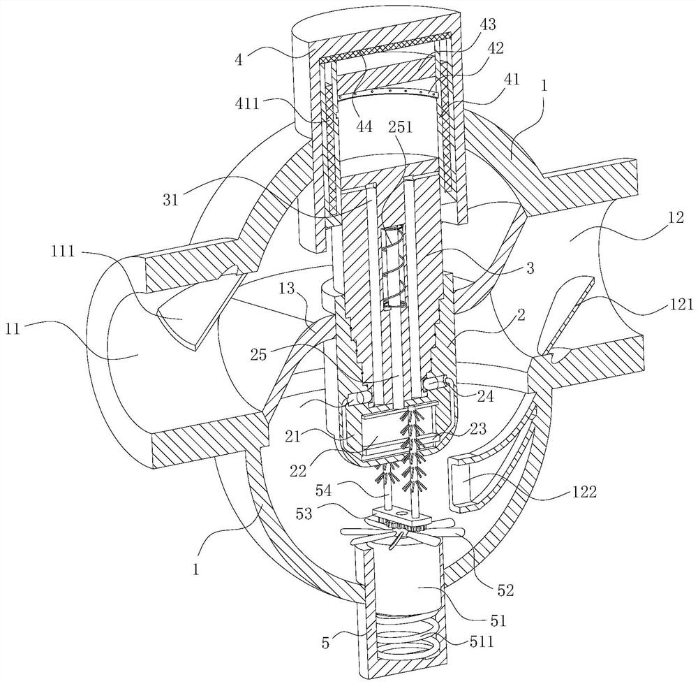
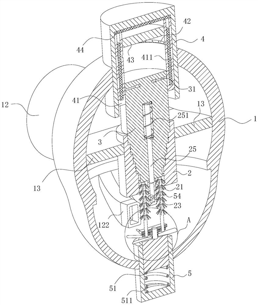
[0038] As an embodiment of the present invention, a sealing ring is arranged on the stepped spool 3; the sealing ring is located on the side of the stepped step at the lower end of the stepped spool 3; between 2;

[0039] When working, when the solenoid valve is connected to the power supply of the coil 411 by the controller, and the stepped valve core 3 is pushed and inserted into the stepped seat 2, the sealing ring provided on the side of the stepped step on the stepped valve core 3 and the step in the stepped seat 2 The side surfaces of the stepped steps contact each other, thereby improving the sealing performance between the stepped valve core 3 and the stepped seat 2. At the same time, the sealing ring can ensure that the wear between the stepped valve core 3 and the stepped seat 2 is serious for a long time, resulting in After the gap between the two is increased, the sealing ring can still ensure that the sealing between the two is on the qualified line, effectively p...


PUM


Abstract

The invention belongs to the technical field of electromagnetic valves, and particularly relates to a two-way electromagnetic valve which comprises a valve body. A first mounting opening and a secondmounting opening are formed in the left side and the right side of the valve body correspondingly; a middle partition plate is installed in the valve body; a stepped base is mounted in the middle of the middle partition plate; an upper mounting base is mounted on the valve body; a coil is mounted in the upper mounting base; a fixed iron core is mounted in the upper mounting base; a stepped valve core is mounted in the upper mounting base; the end, close to the fixed iron core, of the stepped valve core has magnetism; the lower end of the stepped valve core is arranged to be in a stepped shape;and the stepped valve core is right opposite to the stepped base and can be inserted into the stepped base. The electromagnetic valve is simple in structure, flexible in action, low in production cost and high in working reliability.

Description

technical field [0001] The invention belongs to the technical field of solenoid valves, in particular to a two-way solenoid valve. Background technique [0002] The two-way solenoid valves on the market generally have two valve discs, so the processing and assembly conditions of the two valve discs are extremely demanding, otherwise it is not conducive to the sealing of the medium, making the structure of the solenoid valve more complicated and increasing the production cost. In addition, if one of the two valve discs is damaged, the leakage of the medium will occur, resulting in unreliable work. [0003] There are also some technical solutions in the prior art, such as the Chinese patent with the application number CN201821343709.1, which includes electromagnetic components and valve body components. The above-mentioned electromagnetic valve can effectively prevent the backflow of the medium in the process of controlling the use of the fluid, but There is also the followin...

Claims


Application Information

Patent Timeline
IPC IPC(8): F16K3/26F16K3/314F16K3/30F16K31/06F16K49/00F16K27/04H01F27/10B08B9/027B08B1/00
CPCF16K3/267F16K3/314F16K3/30F16K31/0668F16K31/0675F16K49/007F16K27/041F16K27/048H01F27/10B08B9/027B08B1/12
Inventor 吴奇勋蔡士军
Owner 吴奇勋
Learn More