Drainage water quality energy recovery system for thermal equipment and pipelines of thermal power plant

A technology for thermal power plants and thermal equipment, applied in the field of drainage water quality energy recovery system, can solve the problems of thermal drainage energy waste, large pressure difference before and after the trap, and increased heat load of the condenser, etc., so as to prolong the service life, Reduce the degree of scouring wear and reduce the effect of heat transfer temperature difference

Pending Publication Date: 2020-12-04
CEEC HUNAN ELECTRIC POWER DESIGN INST
View PDF0 Cites 2 Cited by
  • Summary
  • Abstract
  • Description
  • Claims
  • Application Information

AI Technical Summary

Problems solved by technology

The system scheme has the following disadvantages: on the one hand, the pressure of the drain expander is basically equal to the back pressure of the condenser, which will lead to a large pressure difference between the front and back of each trap, which will cause great erosion to each trap; on the other hand, the drain After expansion of the expansion vessel, steam and water will be introduced into the condenser or discharged into the atmosphere, which will cause waste of energy in the thermal drainage water; there is also an increase in the thermal load of the condenser after expansion of the expansion vessel, which may cause condensation. Turbine back pressure fluctuations lead to changes in steam turbine output

Method used


Image

  • Drainage water quality energy recovery system for thermal equipment and pipelines of thermal power plant

Examples


Embodiment Construction

[0016] The present invention will be further described in detail below in conjunction with the accompanying drawings and specific embodiments.

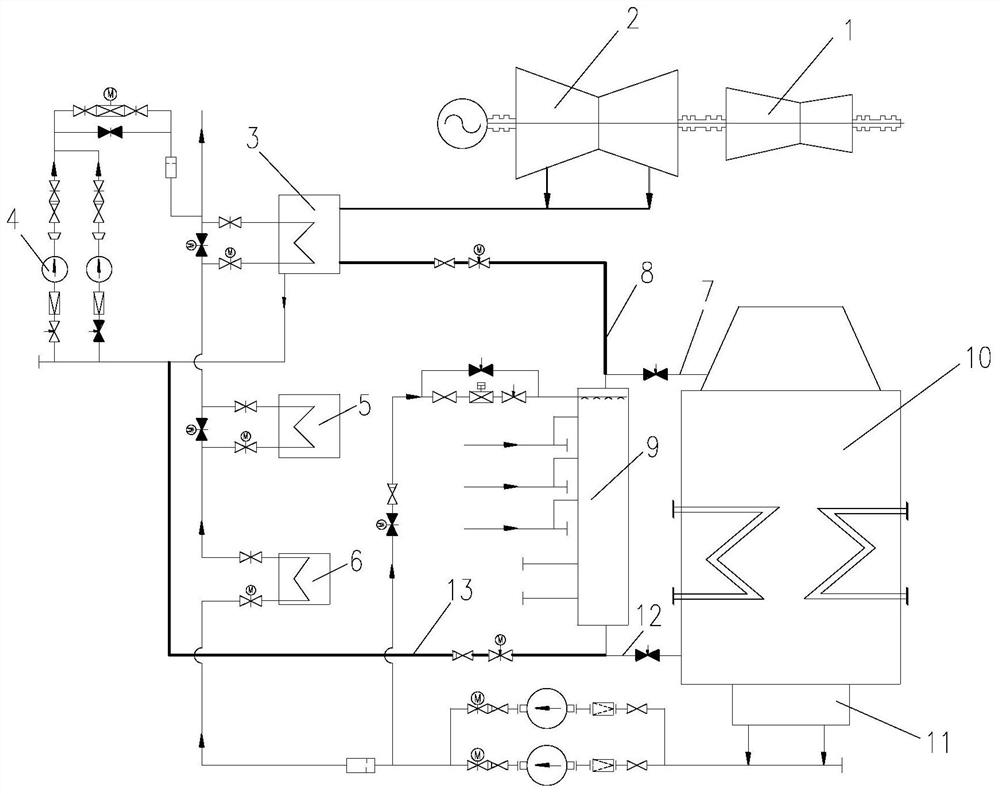
[0017] refer to figure 1 , the present embodiment includes a low pressure drainage pump heat recovery system and a heat engine drainage system. The low pressure steam extraction heat recovery system is connected to the heat engine drainage system. There are drain pump 4, next-end low-pressure heater 3, last-stage low-pressure heater 5 and shaft seal heater 6, drain pump 4 and second-last low-pressure heater 3 are connected in series to form a drain pump branch circuit, and the last-stage low-pressure heater 3. The final low-pressure heater 5 and the shaft seal heater 6 are connected in series to form a heater branch circuit. The heat engine drainage system includes a hydrophobic expansion vessel 9 and a condenser 10. The steam space of the hydrophobic expansion vessel 9 passes through the first exhaust pipe 7 and the condenser. The s...


PUM


Abstract

The invention discloses a drainage water quality energy recovery system for thermal equipment and pipelines of a thermal power plant. The drainage water quality energy recovery system for thermal equipment and pipelines of the thermal power plant comprises a turbine low-pressure steam extraction regenerative system and a heat engine drainage system, the low-pressure steam extraction regenerative system is connected with the heat engine drainage system, a low-pressure heater drainage pump regenerative system comprises a low-pressure heater drainage pump pipeline, and a drainage pump and a secondary last-stage low-pressure heater are arranged on the low-pressure heater drainage pump pipeline. The drainage pump is connected in series with the secondary last-stage low-pressure heater to form adrainage pump branch; the heat engine drainage system comprises a drainage flash tank and a condenser. The steam space of the drainage flash tank is connected with the steam space of the condenser through a first steam exhaust pipeline. The water space of the drainage flash tank is connected with a condenser hot well through a first drainage pipeline; the steam space of the drainage flash tank isconnected with the secondary last-stage low-pressure heater through a second steam exhaust pipeline; and the water space of the drainage flash tank is connected with an inlet pipeline of the drainagepump through a second drainage pipeline. Drainage water can be recycled to a condensation water system, the heat load of a condenser is reduced, and the back pressure behind a thermal drain valve ofa power plant is improved.

Description

technical field [0001] The invention relates to the technical field of thermal power systems in power plants, in particular to a water quality energy recovery system for thermal equipment and pipelines in thermal power plants. Background technique [0002] During the start-up and normal operation of the generator set, thermal drainage water such as frequent drainage, start-stop drainage, emergency drainage and overflow water will be generated in the thermal equipment and pipelines of the power plant. Thermal drainage of thermal equipment and pipelines in power plants, such as frequent drainage, start-stop drainage, emergency drainage and overflow water, etc., are expanded through unit drainage expansion vessels to form lower pressure steam space and water space, and finally re-enter the unit thermal system middle. [0003] In the traditional design scheme of the drainage system, the drainage water of the equipment and pipelines is expanded through the unit drainage expansio...

Claims


Application Information

Patent Timeline
Patent Type & Authority Applications(China)
IPC IPC(8): F22B37/50F22D1/50F28B1/02F28B9/08F28D7/08
CPCF22B37/50F22D1/50F28B1/02F28B9/08F28D7/082
Inventor 唐磊李学军许啸刘霞朱伟民
Owner CEEC HUNAN ELECTRIC POWER DESIGN INST
Why Eureka
Try Eureka