Flame ion signal compensation circuit and control method
A flame ion and signal compensation technology, applied in the direction of combustion method, electric pulse generator circuit, combustion ignition, etc., can solve problems affecting user experience, weakening of flame ion signal, accidental flameout protection, etc., to improve customer experience, Prevent false flameout and improve reliability
- Summary
- Abstract
- Description
- Claims
- Application Information
AI Technical Summary
Problems solved by technology
Method used
Image

Examples
Embodiment 1
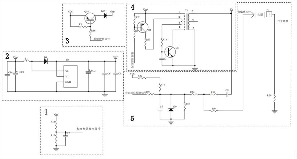
[0028] Embodiment 1 provides a flame ion signal compensation circuit, such as figure 1 As shown, it is used to compensate the battery power of the pulse igniter, which includes a voltage detection module 1, a boost module 2, a compensation module 3, an oscillation transformer module 4, a flame detection module 5 and a control unit, the control unit and The voltage detection module 1, the compensation module 3, the oscillation transformer module 4 and the flame detection module 5 are all electrically connected, the compensation module 3 is electrically connected to the boost module 2, and the oscillation The transformer module 4 is electrically connected to the flame detection module 5;
[0029] In this way, using the above circuit, the control unit controls the voltage detection module 1 to obtain the battery voltage signal Vbat, and then generates a compensation control signal according to the battery voltage signal Vbat to control the conduction of the compensation module 3,...
Embodiment 2
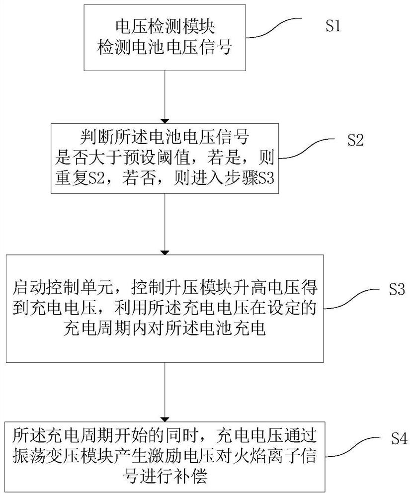
[0038] A control method of a flame ion signal compensation circuit, the method is implemented by operating the flame ion signal compensation circuit, such as figure 2 As shown, the control method shown includes the following steps:
[0039] S1, the voltage detection module detects the battery voltage signal Vbat;
[0040] S2, judging whether the battery voltage signal Vbat is greater than a preset threshold Vset, if yes, repeating S2, if not, entering step S3;
[0041] S3, start the control unit, control the boost module 2 to increase the voltage to obtain a charging voltage Vcc, and use the charging voltage Vcc to charge the battery within the set charging period T;
[0042] S4, when the charging cycle T starts, the charging voltage Vcc generates a high voltage pulse Vp through the oscillation transformer module 4 to compensate the flame ion signal.
[0043] This embodiment monitors the power of the battery in real time. When it is detected that the battery voltage drops t...
PUM
 Abstract
Description
Claims
Application Information
 - R&D
- Intellectual Property
- Life Sciences
- Materials
- Tech Scout
- Unparalleled Data Quality
- Higher Quality Content
- 60% Fewer Hallucinations
Browse by: Latest US Patents, China's latest patents, Technical Efficacy Thesaurus, Application Domain, Technology Topic, Popular Technical Reports.
© 2025 PatSnap. All rights reserved.Legal|Privacy policy|Modern Slavery Act Transparency Statement|Sitemap|About US| Contact US: help@patsnap.com