Efficient condenser

A condenser and high-efficiency technology, used in evaporators/condensers, refrigerators, refrigeration components, etc., can solve the problems of slow condensation efficiency and influence of condensation effect, and achieve the purpose of increasing heat exchange time, reducing temperature, and fully releasing heat. Effect

Inactive Publication Date: 2020-12-04
上海一冷特艺压力容器有限公司
View PDF10 Cites 2 Cited by
  • Summary
  • Abstract
  • Description
  • Claims
  • Application Information

AI Technical Summary

Problems solved by technology

[0004] The inventor found that during the use of the above-mentioned condenser, the high-temperature gaseous refrigerant is in contact with the high-temperature section and the low-temperature section of the brine at the same time, and the temperature of the brine in the low-temperature section rises faster, and the condensation of the gas refrigerant in the high-temperature section The effect has an impact, making the condensation efficiency relatively slow, which has a greater impact on the overall refrigeration system

Method used


Image

  • Efficient condenser
  • Efficient condenser
  • Efficient condenser

Examples


Embodiment Construction

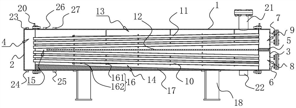
[0031] The following is attached Figure 1-3 The application is described in further detail.

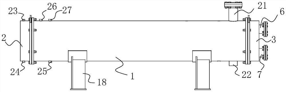
[0032] The embodiment of the present application discloses a high-efficiency condenser. refer to figure 1 and figure 2 , a high-efficiency condenser includes a cylindrical shell 1, a left end cover 2 and a right end cover 3, the left end cover 2 and the right end cover 3 are installed on both ends of the shell 1 through flanges, the left end cover 2 and the shell 1 A left chamber 4 is formed between the ends of the right end cover 3, a baffle plate 5 is welded horizontally in the right end cover 3, a water inlet pipe 6 and an outlet pipe 7 are respectively welded at the ends of the right end cover 3, and the water inlet pipe 6 is located at the bottom of the right end cover 3 On one side, a water inlet chamber 8 is formed between the baffle plate 5 and the part of the right end cover 3 close to the water inlet pipe 6, and a water outlet chamber 9 is formed between the baffle plat...


PUM


Abstract

The invention discloses an efficient condenser. The efficient condenser comprises a shell, a left end cover and a right end cover, the left end cover and the right end cover are fixedly installed at the two ends of the shell, a left cavity is formed between the left end cover and the end portion of the shell, a baffle is arranged in the right end cover, and the end portion of the right end cover is connected with a water inlet pipe and a water outlet pipe. An air inlet pipe is installed on the top of the shell, and a liquid outlet pipe is installed at the bottom of the shell. A water inlet heat exchange pipe is connected between the left cavity and a water inlet cavity, and a water outlet heat exchange pipe is connected between the left cavity and a water outlet cavity. A partition plate is installed in the shell and divides the shell into an upper cavity and a lower cavity, flow guide structures are installed in the upper cavity and the lower cavity, and each flow guide structure comprises a flow guide plate and a fixing screw rod. One end of each fixing screw rod is arranged on the end face of the shell, and the flow guide plates are sequentially, alternately and fixedly installed on the fixing screw rods. According to the efficient condenser, the motion track of gaseous refrigerants is prolonged, the heat exchange time of the gaseous refrigerants is prolonged, the gaseous refrigerants can release heat more sufficiently, and the condensation efficiency is improved.

Description

technical field [0001] The present application relates to the field of condensers, in particular to a high-efficiency condenser. Background technique [0002] The condenser is a component of the refrigeration system and is a type of heat exchanger that can convert gas or vapor into liquid, and transfer the heat in the tube to the air near the tube in a very fast manner. [0003] For example, the Chinese invention patent application document with the application number CN201510758473.2 discloses a horizontal shell-and-tube condenser. The condenser includes a shell, a heat exchange tube, a flange, and an end cover. The shell is divided into a left shell The body and the right shell, the left shell and the right shell are connected by flanges, heat exchange tubes are arranged in the left shell and the right shell, the end cover is divided into a left end cover and a right end cover, and the left end of the left shell is connected to the left end cover , the upper part of the l...

Claims


Application Information

Patent Timeline
Patent Type & Authority Applications(China)
IPC IPC(8): F25B39/04F28F9/22F28F9/24
CPCF25B39/04F25B2339/04F25B2500/09F28F9/22F28F9/24F28F2009/226
Inventor 殷伟明程跃
Owner 上海一冷特艺压力容器有限公司
Why Eureka
Try Eureka