Automatic feeding device for end face machining

A technology of automatic feeding and end surface processing, which is applied in the field of parts processing, can solve problems such as the time-consuming shutdown and start-up process, the difficulty in adapting to large-volume production needs, and the impact on equipment life, so as to achieve low equipment cost and high degree of automation , The effect of reducing the cost of equipment

Active Publication Date: 2021-04-30
襄阳鼎超机械制造有限公司
View PDF15 Cites 1 Cited by
  • Summary
  • Abstract
  • Description
  • Claims
  • Application Information

AI Technical Summary

Problems solved by technology

[0002] In the process of processing and preparing plate-shaped parts, it is usually necessary to finish the end face. At present, milling machines are mostly used for end-face finishing of plate-shaped parts. Usually, milling machines can only process one part at a time. First, through The fixture fixes the part on the workbench of the machine tool, and then starts the machine tool for processing, but this method can only process one part at a time, and requires frequent loading and unloading by the operator, which is labor-intensive and has low processing efficiency, making it difficult to adapt High-volume production needs
[0003] The utility model patent with the authorized notification number CN211332327U discloses a double-end synchronous finishing tooling system for multiple zinc-aluminum alloy parts, including a clamping frame, which is provided with a number of stations for placing parts, and tool settings On the outside of the clamping frame, a tool is arranged on opposite sides of the clamping frame, and the tool is set on the sliding mechanism to make the tool move in a direction perpendicular to the clamping frame, so that the end faces of the parts on both sides can be processed simultaneously , although this kind of tooling can realize multiple parts clamping at one time, but when this kind of tooling is clamping parts, it needs to be manually operated after stopping to position the parts in sequence, which is inefficient, and the frequent start and stop of the machine affects the life of the equipment , and it still takes a lot of time to shut down and start up

Method used


Image

  • Automatic feeding device for end face machining
  • Automatic feeding device for end face machining
  • Automatic feeding device for end face machining

Examples


Embodiment Construction

[0032] The technical solutions of the present invention will be clearly and completely described below in conjunction with specific embodiments. Apparently, the described embodiments are only some of the embodiments of the present invention, not all of them. Based on the embodiments of the present invention, all other embodiments obtained by persons of ordinary skill in the art without creative efforts fall within the protection scope of the present invention.

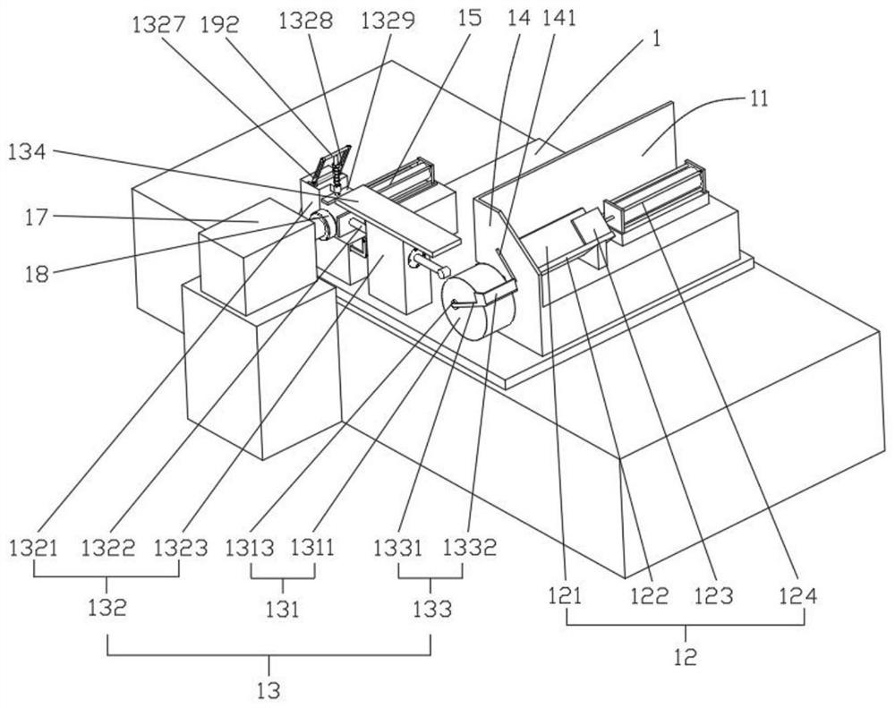
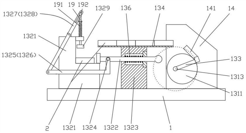
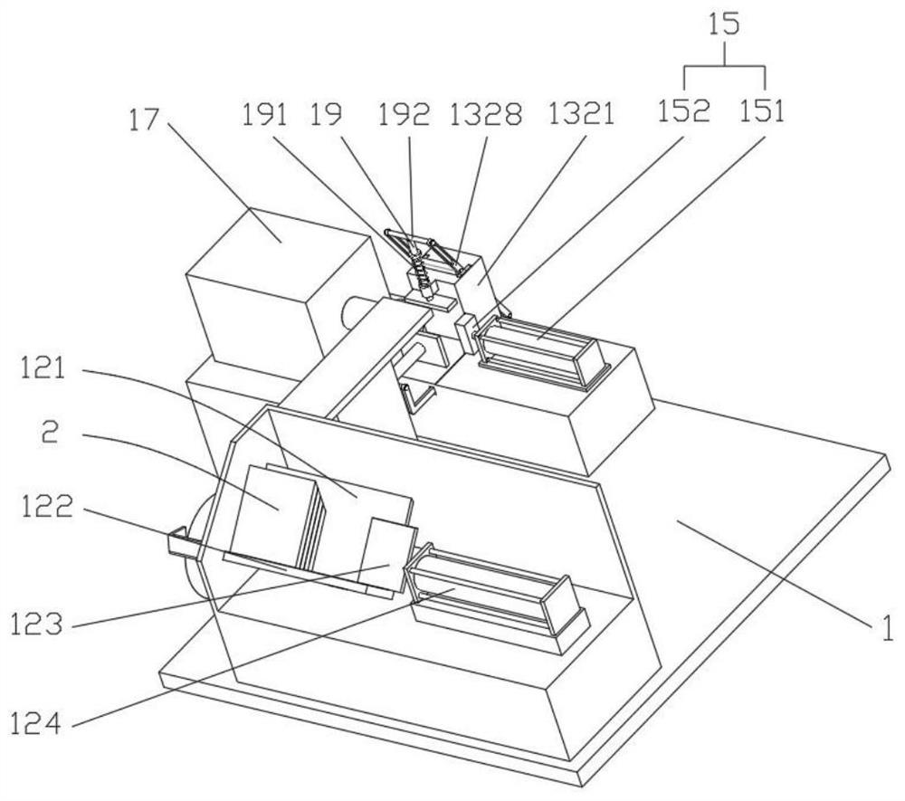
[0033] refer to Figure 1 ~ Figure 3 , an automatic feeding device for end surface processing, including a body 1 fixed on the machine tool table, the body 1 includes a support frame 11 vertically fixed on the machine tool table, one side of the support frame 11 is provided for continuous The pushing device 12 for feeding, the other side of the support frame 11 is provided with an automatic positioning device 13 for transporting the workpiece 2 to the processing position and automatically clamping, and one side of the...


PUM


Abstract

The invention relates to the technical field of part machining, and discloses an automatic feeding device for end face machining. The automatic feeding device for end face machining comprises a pushing device, an automatic positioning device and a discharging device, wherein workpieces to be machined are continuously conveyed to the automatic positioning device through the pushing device so as to be positioned and clamped, and discharging is conducted through the discharging device, so that the continuous and automatic end face machining procedure is achieved, the automation degree is high, and the working efficiency is high; in addition, a conveying mechanism in the automatic positioning device drives a conveying wheel to do eccentric rotating motion through an eccentric shaft, so that clamping of the workpieces is achieved; in the workpiece conveying motion process of the conveying wheel, on one hand, the workpiece conveying path is increased, and the diameter of the conveying wheel needed for conveying the workpieces with the same size is reduced, so that the equipment size is reduced, and the equipment cost is reduced; on the other hand, the conveying wheel can drive a positioning mechanism to position the workpieces in the eccentric movement process, so that the synchronism between the positioning mechanism and the conveying mechanism is guaranteed; and the positioning mechanism does not need extra power, so that the equipment cost is low.

Description

technical field [0001] The invention relates to the technical field of parts processing, in particular to an automatic feeding device for end surface processing. Background technique [0002] In the process of processing and preparing plate-shaped parts, it is usually necessary to finish the end face. At present, milling machines are mostly used for end-face finishing of plate-shaped parts. Usually, milling machines can only process one part at a time. First, through The fixture fixes the part on the workbench of the machine tool, and then starts the machine tool for processing, but this method can only process one part at a time, and requires frequent loading and unloading by the operator, which is labor-intensive and has low processing efficiency, making it difficult to adapt High-volume production needs. [0003] The utility model patent with the authorized notification number CN211332327U discloses a double-end synchronous finishing tooling system for multiple zinc-alum...

Claims


Application Information

Patent Timeline
Patent Type & Authority Applications(China)
IPC IPC(8): B23Q7/00B23Q3/18
CPCB23Q7/00B23Q3/18
Inventor 伍继超田江
Owner 襄阳鼎超机械制造有限公司
Why Eureka
Try Eureka