In-service large-span structure rod piece axial force testing component

A structural rod and axial force technology, which is applied to the field of axial force testing components of large-span structural rods in service, can solve the problems of high operation difficulty, adverse effects on sensor working stability and service life, and high labor intensity, so as to improve the work efficiency. Effects of stability and longevity

Active Publication Date: 2020-12-04
LIAONING TECHNICAL UNIVERSITY
View PDF5 Cites 0 Cited by
  • Summary
  • Abstract
  • Description
  • Claims
  • Application Information

AI Technical Summary

Problems solved by technology

However, the above-mentioned various sensors used to monitor the axial force of the rods are all installed on the surface of the rods after the rods are lapped and assembled. It is realized through a large number of high-altitude operations, which are difficult and labor-intensive, and because the sensors are directly installed on the surface of the rod, external environmental factors such as bad weather will have a negative impact on the working stability and service life of the sensor.

Method used


Image

  • In-service large-span structure rod piece axial force testing component
  • In-service large-span structure rod piece axial force testing component
  • In-service large-span structure rod piece axial force testing component

Examples


Embodiment Construction

[0019] The present invention will be further described in detail below in conjunction with the accompanying drawings and specific embodiments.

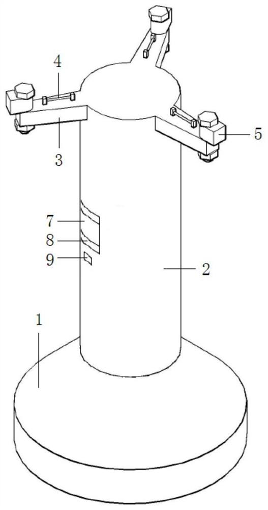
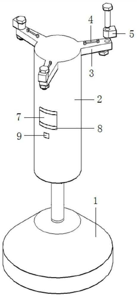
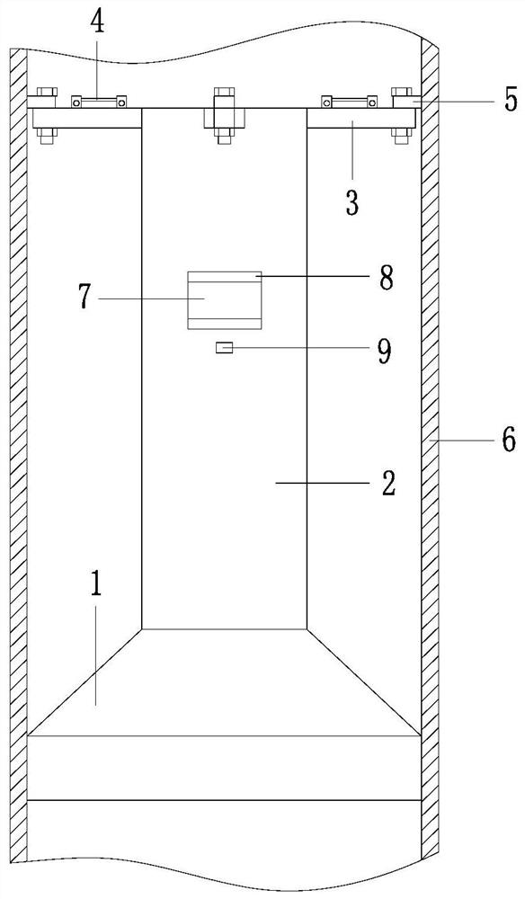
[0020] Such as Figure 1~6 As shown, an axial force test component of a long-span structural rod in service includes a support base 1, a support beam 2, a cantilever beam 3, an optical fiber grating 4 and an adapter block 5; the support base 1 and the rod to be tested 6 The inner surfaces are welded and fixed together, one end of the support beam 2 is fixedly inserted on the support base 1, the support beam 2 is parallel to the rod 6 to be tested, and one end of the cantilever beam 3 is welded and fixed to the other end of the support beam 2 Together, the cantilever beam 3 is perpendicular to the support beam 2, one end of the adapter block 5 is screwed and fixedly connected to the other end of the cantilever beam 3, and the other end of the adapter block 5 is welded and fixedly connected to the inner surface of the rod 6 to be tested...


PUM


Abstract

The invention relates to an in-service large-span structure rod piece axial force testing component. The component comprises a supporting seat, a supporting beam, a cantilever beam, a fiber bragg grating and a switching block; and the supporting seat is welded and fixedly connected with the inner surface of a rod piece to be tested, one end of the supporting beam is fixedly connected with the supporting seat in an inserted mode, the supporting beam is parallel to the rod piece to be tested, one end of the cantilever beam is fixedly connected with the other end of the supporting beam in a welded mode, the cantilever beam is perpendicular to the supporting beam, one end of the switching block is fixedly connected with the other end of the cantilever beam in a screwed mode, the inner surfaceof the rod piece to be tested is fixedly connected with the switching block, and the fiber bragg grating is fixedly installed on the upper surface of the cantilever beam and is parallel to the cantilever beam. The testing component is installed in the rod piece to form an integrated structure with a rod body, and installation can be completed in the rod piece machining and production stage, so thesituation that external environment factors such as an aerial work installation mode and severe weather difficultly influence an axial force test component is avoided, the work stability is improved,and the service life is prolonged. And a piezoelectric sensing device is additionally arranged in the testing component, so that the strain of the large-span structural rod piece under the dynamic load can be monitored.

Description

technical field [0001] The invention belongs to the technical field of building structure health monitoring, and in particular relates to an axial force testing member of a long-span structural bar in service. Background technique [0002] In recent years, long-span structures have developed rapidly and should be widely used in iconic buildings such as the Bird's Nest and the Water Cube. However, due to the complex construction engineering and long life cycle of long-span structures, the health monitoring of long-span structures is very important. [0003] For construction projects with long-span structures, long-term tracking and monitoring should be carried out from the construction stage, and in the service stage, due to the long-term working conditions of the long-span structure, important components of the long-span structure are prone to damage and other special circumstances. Therefore, in order to effectively monitor the health of the entire long-span structure, the...

Claims


Application Information

Patent Timeline
IPC IPC(8): G01L1/24G01B11/16G01L1/16G01B7/16
CPCG01L1/242G01B11/165G01L1/16G01B7/16
Inventor 殷志祥李国皓
Owner LIAONING TECHNICAL UNIVERSITY
Why Eureka
Try Eureka