
Method for preventing hot working medium from reversely flowing in liquid supply pipe in defrosting of air cooler

A technology of air cooler and thermal working medium, which is applied in the direction of refrigerators, refrigeration and liquefaction, cooling fluid circulation devices, etc., which can solve the problem of increasing the resistance loss of refrigerant, increasing the gas content in refrigerant liquid, and reducing the flow rate of refrigerant and other issues, to achieve the effect of improving the service life and working stability, and improving the cooling effect

Active Publication Date: 2019-08-27
CHINA UNITED ENG
View PDF12 Cites 0 Cited by
  • Summary
  • Abstract
  • Description
  • Claims
  • Application Information

AI Technical Summary

Problems solved by technology

If a check valve is installed on the inlet side of the thermal expansion valve, when the thermal medium defrosts, the thermal medium will flow through the thermal expansion valve in reverse, which will affect the working stability and service life of the thermal expansion valve; When the thermal medium defrosts, the thermal medium will not flow through the thermal expansion valve in reverse, but when the air cooler is cooling normally, the check valve installed on the outlet side of the thermal expansion valve will increase the thermal expansion. The resistance loss of the two fluid refrigerants flowing out of the valve will reduce the flow rate of the refrigerant and increase the gas content in the refrigerant liquid, which will seriously affect the cooling effect of the air cooler and the operating performance of the refrigeration system

Method used


Image

  • Method for preventing hot working medium from reversely flowing in liquid supply pipe in defrosting of air cooler

Examples


Embodiment Construction

[0015] The present invention will be further described in detail below in conjunction with the accompanying drawings and examples. The following examples are explanations of the present invention and the present invention is not limited to the following examples.

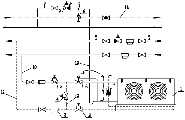
[0016] see figure 1 , a method for preventing the backflow of thermal working medium in the liquid supply pipe when the air cooler defrosts, the liquid supply solenoid valve 5 and The thermal expansion valve 6 is provided with a gas filter 3, a defrosting solenoid valve 2 and a defrosting one-way valve 7 on the thermal medium defrosting pipeline 11 connected to the air cooler 1 and the oil separator outlet pipe, and is connected with the cold wind A return air solenoid valve 9 is provided on the air return pipeline 13 connected to the air inlet pipe of the machine 1 and the gas-liquid separator, and a liquid discharge overflow valve is provided on the liquid discharge pipeline 14 connected to the air return pipeline...


PUM


Abstract

The invention provides a method for preventing a hot working medium from reversely flowing in a liquid supply pipe in defrosting of an air cooler. When the hot working medium is defrosted, the hot working medium does not reversely flow through a thermostatic expansion valve, and in normal cooling, the cooling effect of the air cooler and the operation performance of a cooling system are not influenced. A pressing pipeline is additionally arranged between a liquid supply pipeline and a hot working medium defrosting pipeline, the connection part between the pressing pipeline and the liquid supply pipeline is positioned between a liquid supply solenoid valve and the thermostatic expansion valve, the connection part between the pressing pipeline and the hot working medium defrosting pipeline is positioned between a gas filter and a defrosting solenoid valve, and a pressing solenoid valve is mounted on the pressing pipeline, and replaces a check valve on an inlet side or an outlet side of the thermostatic expansion valve in the current engineering design, so that the service life of the thermostatic expansion valve is prolonged, the working stability of the thermostatic expansion valveis improved, the cooling effect of the air cooler is improved, and the operation performance of the cooling system is improved.

Description

technical field [0001] The invention relates to a method for preventing thermal working fluid from flowing backward in a liquid supply pipe when an air cooler defrosts, which is used in a cold chain logistics refrigerator. Background technique [0002] In the current cold chain logistics industry, due to the advantages of compact structure and fast cooling speed, the air cooler has been widely used in cold chain logistics cold storage, as shown in the Chinese patent application number 201220124094.X. When the temperature of the outer surface of the fins of the air cooler is lower than 0°C, frost will form on the heat transfer tubes of the air cooler and the outer surface of the fins, forming thermal resistance and increasing the energy consumption coefficient of the refrigeration system. In large and medium-sized low-temperature cold storage systems, thermal fluid defrosting is a commonly used method of defrosting. A check valve is installed on the inlet or outlet side of t...

Claims


Application Information

Patent Timeline
IPC IPC(8): F25D17/04F25D21/06F25D21/14F25B41/04F25B41/06F25B43/00F25B41/20F25B41/31
CPCF25D17/04F25B43/003F25D21/06F25D21/14F25B41/31F25B41/20
Inventor 靳新春
Owner CHINA UNITED ENG
Learn More