
IO drive circuit in pulse mode

A technology of driving circuit and pulse mode, which is applied in the direction of electric pulse generator circuit and active components to generate pulses, etc., can solve the problems of poor reliability, incorrect operation of the post-stage actuator, uncontrollable level state, etc., to prevent The effect of false output

Pending Publication Date: 2020-12-04
徐工汉云技术股份有限公司
View PDF6 Cites 0 Cited by
  • Summary
  • Abstract
  • Description
  • Claims
  • Application Information

AI Technical Summary

Problems solved by technology

[0002] At present, in conventional industrial or automotive environments, GPIO ports are generally used as system input and output, which is simple and efficient. For example, relay drive circuits and electric heating tube heating circuits. At present, the output circuits of market products generally use relatively simple drive circuits. The drive circuit uses the high and low level status of the IO port to directly complete the control. The structure is relatively simple and can meet the conventional needs, but the reliability is relatively poor. In industries with high reliability requirements, it cannot meet the needs.
[0003] Since the current IO drive circuit uses the IO port level state (high level or low level) for control, when the controller is abnormal, the IO port will still be in a certain state of high or low level. The state of this level is uncontrollable, which will cause the subsequent actuators to perform incorrect actions

Method used


Image

  • IO drive circuit in pulse mode

Examples


Embodiment Construction

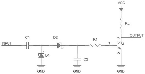
[0012] Such as figure 1 A pulse mode IO driving circuit shown is characterized in that it includes an input port INPUT, a capacitor C1, a capacitor C2, a diode D1, a diode D2, a resistor R1, a transistor Q, a load RL and an output port OUTPUT; the input port INPUT is connected to Capacitor C1, capacitor C1 is connected to the cathode of diode D1 and the anode of diode D2, the cathode of diode D2 is connected to resistor R1 and capacitor C2, the other section of resistor R1 is connected to the base of transistor Q, and the collector of transistor Q is connected to the load RL and the output port OUTPUT, the emitter of the transistor Q, the other end of the capacitor C2 and the anode of the diode D1 are grounded, and the other end of the load RL is connected to the power supply voltage VCC.

[0013] The load RL is a light emitting diode, a relay or any electronic device.

[0014] The capacitor C1 acts as a DC block, converting the pulse signal into an AC signal and shielding th...


PUM


Abstract

The invention relates to a pulse mode IO drive circuit, and belongs to the technical field of controllers. The circuit comprises an input port INPUT, a capacitor C1, a capacitor C2, a diode D1, a diode D2, a resistor R1, a triode Q, a load RL and an output port OUTPUT. The input port INPUT is connected with the capacitor C1, the capacitor C1 is connected with the cathode of the diode D1 and the anode of the diode D2, the cathode of the diode D2 is connected with the resistor R1 and the capacitor C2, the other end of the resistor R1 is connected with the base of a triode Q, the collector of thetriode Q is connected with a load RL and an output port OUTPUT, the emitter of the triode Q, the other end of the capacitor C2 and the anode of the diode D1 are connected to ground, and the other endof the load RL is connected with a power supply voltage VCC. The circuit has the advantages that the load is driven in the mode that the direct-current pulse voltage is converted into the alternating-current pulse voltage and then rectified and output into the direct-current voltage; the circuit only acts on pulse signals while does not act on fixed level signals, so that error output caused by dead halt of a controller is effectively prevented.

Description

technical field [0001] The invention relates to an IO driving circuit in a pulse mode, belonging to the technical field of controllers. Background technique [0002] At present, in conventional industrial or automotive environments, GPIO ports are generally used as system input and output, which is simple and efficient. For example, relay drive circuits and electric heating tube heating circuits. At present, the output circuits of market products generally use relatively simple drive circuits. The drive circuit uses the high and low level status of the IO port to directly complete the control. The structure is relatively simple and can meet the conventional needs, but the reliability is relatively poor. In industries with high reliability requirements, it cannot meet the needs. [0003] Since the current IO drive circuit uses the IO port level state (high level or low level) for control, when the controller is abnormal, the IO port will still be in a certain state of high or...

Claims


Application Information

Patent Timeline
Patent Type & Authority Applications(China)
IPC IPC(8): H03K3/021
CPCH03K3/021
Inventor 宫坤张启亮姜丽萍郭辉韩华明刘新峰刘振
Owner 徐工汉云技术股份有限公司
Learn More