
Self-cleaning type dust collection pipeline for textile dust collection equipment

A dust-absorbing pipe and self-cleaning technology, applied in the textile field, can solve problems such as heavy workload, increased production costs, and poor air circulation

Active Publication Date: 2020-12-08
湖南科创纺织股份有限公司
View PDF6 Cites 8 Cited by
  • Summary
  • Abstract
  • Description
  • Claims
  • Application Information

AI Technical Summary

Problems solved by technology

[0003] When the vacuum equipment is used to clean up the dust such as cotton wool, the cotton wool is usually taken outdoors through the vacuum pipe, and in order to prevent the cotton wool from polluting the air again, it is necessary to A filter is installed in the suction pipe to block the dust, but when the dust is blocked for a long time, a large amount of dust will accumulate on the filter, making the air circulation poor, which in turn reduces the dust collection efficiency in the textile workshop, and when When there is a lot of dust accumulated on the filter, the work load of the dust collection equipment is heavy at this time, which may easily cause damage to the dust collection equipment and increase production costs

Method used


Image

  • Self-cleaning type dust collection pipeline for textile dust collection equipment
  • Self-cleaning type dust collection pipeline for textile dust collection equipment

Examples


Embodiment Construction

[0018] In order to make the above objects, features and advantages of the present invention more comprehensible, specific implementations of the present invention will be described in detail below in conjunction with the accompanying drawings. In the following description, numerous specific details are set forth in order to provide a thorough understanding of the present invention. However, the present invention can be implemented in many other ways different from those described here, and those skilled in the art can make similar improvements without departing from the connotation of the present invention, so the present invention is not limited by the specific implementations disclosed below.

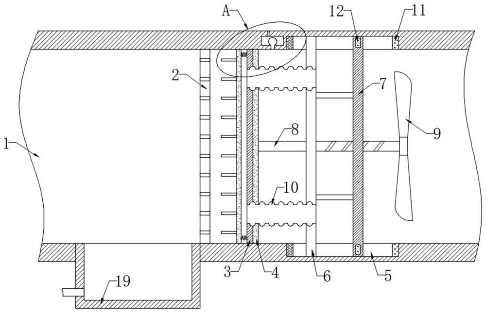
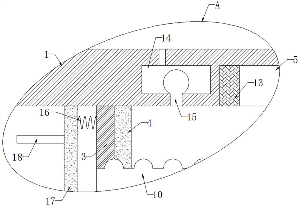
[0019] refer to Figure 1-2 , a self-cleaning dust suction pipe for textile dust suction equipment, comprising a pipe body 1, a filter plate 2 is fixedly connected to the inner wall of the pipe body 1, a fixed plate 3 is fixedly connected to the inner wall of the pipe body 1, and a fi...


PUM


Abstract

The invention discloses a self-cleaning type dust collection pipeline for textile dust collection equipment. The self-cleaning type dust collection pipeline for the textile dust collection equipment comprises a pipe body. A filter plate is fixedly connected to the inner wall of the pipe body, a fixed plate is fixedly connected to the inner wall of the pipe body, a permanent magnet plate is fixedlyconnected to the side wall of the fixed plate, an annular groove is formed in the inner wall of the pipe body, and a sliding plate is hermetically and slidably connected to the inner wall of the annular groove. The side wall of the sliding plate is fixedly connected with a vertical rod through connecting rods, the vertical rod is slidably connected with the inner wall of the annular groove, the side wall of the permanent magnet plate is rotatably connected with a lead screw, and one end of the lead screw is fixedly connected with fan blades. When filter holes in the filter plate are blocked,the sliding plate slides leftwards to extrude piezoelectric ceramic, so that the piezoelectric ceramic charges and breaks down a parallel plate capacitor formed between the fixed plate and the slidingplate, the permanent magnet plate is demagnetized under the action of heat generated after breakdown, and a magnetic plate slides leftwards under the action of springs. Ejector pins are inserted intothe filter holes to push out dust from the filter holes and clean the filter holes.

Description

technical field [0001] The invention relates to the technical field of textiles, in particular to a self-cleaning dust suction pipe for textile dust collection equipment. Background technique [0002] Textile is the general term for spinning and weaving. During the textile production process, the cotton wool on the yarn will continue to float in the textile workshop. In order to ensure the cleanliness of the workshop and the health of the staff, it is necessary to use vacuum equipment to clean the cotton wool Dust is cleaned by adsorption. [0003] When the dust collection equipment is used to clean up dust such as cotton wool, the cotton wool is often taken outdoors through the vacuum pipe, and in order to prevent the cotton wool from polluting the air again, it is necessary to install a filter in the vacuum pipe to block the dust, but for a long time When the dust is blocked, a large amount of dust will accumulate on the filter, which will make the air circulation poor, a...

Claims


Application Information

Patent Timeline
IPC IPC(8): B08B15/00B01D46/10B01D46/00
CPCB08B15/00B01D46/10B01D46/66
Inventor 高世壮
Owner 湖南科创纺织股份有限公司
Learn More