
A load-bearing member for timber construction

A technology for load-bearing components and buildings, applied in building components, building structures, buildings, etc., can solve the problems of high economic cost, complicated replacement and maintenance construction, etc., and achieve the effect of low investment cost, reasonable overall structure, and reduced construction and maintenance costs.

Active Publication Date: 2021-12-14
DALI UNIV
View PDF10 Cites 0 Cited by
  • Summary
  • Abstract
  • Description
  • Claims
  • Application Information

AI Technical Summary

Problems solved by technology

After damage, the replacement and maintenance of wooden components is cumbersome, and if the structural components are replaced as a whole, the economic cost is also high

Method used


Image

  • A load-bearing member for timber construction
  • A load-bearing member for timber construction
  • A load-bearing member for timber construction

Examples


Embodiment 1

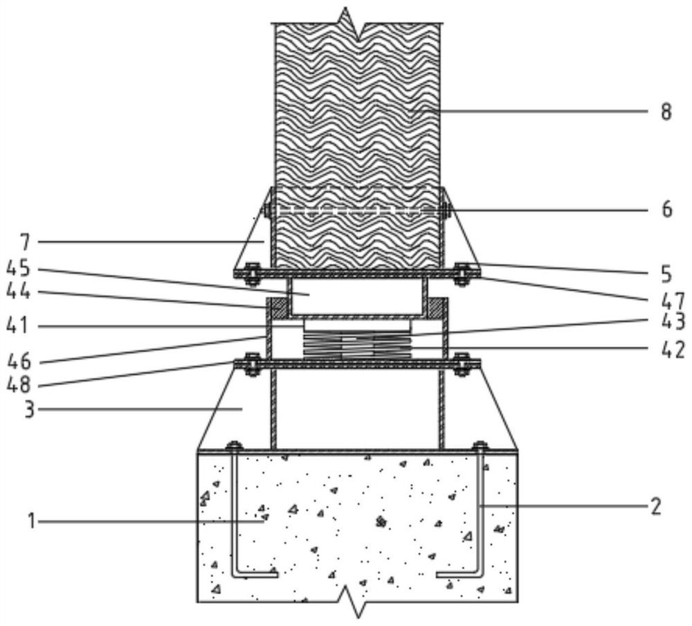
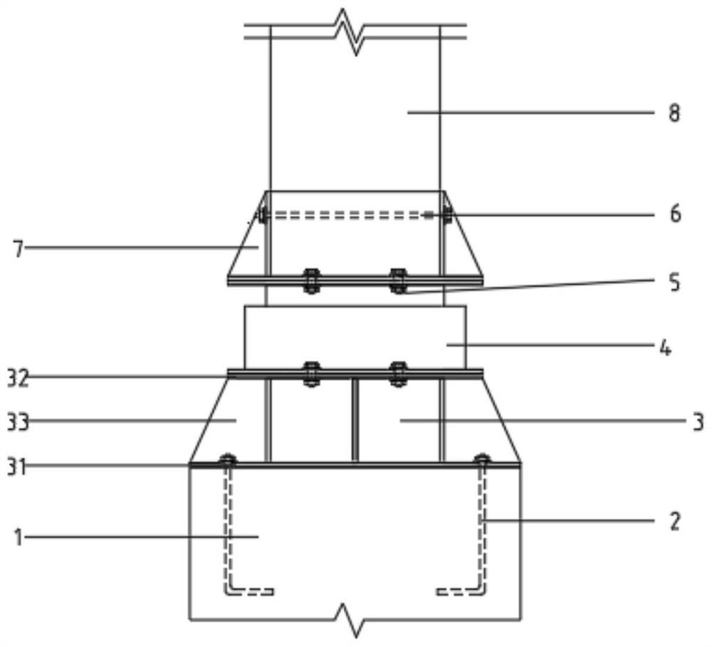
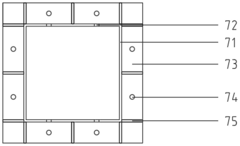
[0039] like figure 1 and figure 2 As shown, a load-bearing component for wooden buildings provided by the present invention includes a base 3, the base 3 is arranged above the concrete foundation 1, and an embedded part 2 is arranged in the concrete foundation 1, and one end of the embedded part 2 It is fixed in the concrete foundation 1, and the other end extends above the base 3 to achieve a fixed connection with the base 3.

[0040] As a further preferred solution, the embedded part 2 is a high-strength stainless steel connecting bolt.

[0041] As a further preferred solution, the concrete foundation 1 may be a prefabricated foundation or a cast-in-place foundation.

[0042] Wherein, as a further preferred solution, the structural composition of the base 3 includes:

[0043] The fourth flange 31 has a plurality of mounting holes 5 evenly distributed thereon, and the mounting holes 5 are used for piercing the embedded parts 2 to realize the fixed connection with the conc...

Embodiment 2

[0068] In order to achieve multi-stage shock absorption on the vibration propagation path and to reduce the impact of vibration on the entire structure step by step, a bean bag damper for buffering vibration is fixed inside the cylinder 4 33 .

[0069] It is also possible to directly use the cylinder 433 as a shock-absorbing cavity, and then place a variety of mixed-sized particle dampers inside it, which are used to reduce the energy of the vibration by colliding with each other during the vibration, so as to realize the anti-vibration effect. buffer.

[0070] The invention provides a load-bearing member for wooden buildings, the overall structure is reasonable, the load-bearing member is a combined structure, the construction time is less when replacing, and the investment cost is low, and the flexible replacement and rapid assembly of wooden components can also be realized. Significantly reduce construction strength and construction maintenance costs. The structure of the ...


PUM


Abstract

The invention relates to a load-bearing component for wooden buildings, which includes a base, a connecting seat is arranged above the base, and a shock-absorbing structure is arranged between the connecting seat and the base, which includes: a first flange, on which a plurality of Installation hole one; cylinder one, the lower end of which is fixed on the first flange; viscous damping liquid, which is filled in cylinder one; cylinder two, which is set in cylinder one and the lower end of cylinder two is immersed in viscous damping liquid Inside; the sealing element is arranged between the cylinder body 2 and the cylinder body 1; the connection plate is fixed on the lower end surface of the cylinder body 2; the column body is vertically arranged and coaxially fixed with the connection plate; body, and one end of it is fixed to the connection plate, and the other end is fixed to the inner bottom surface of the cylinder body one; the second flange has a plurality of mounting holes two evenly distributed on it, and the second flange is fixed on the upper end of the cylinder body two . The invention has reasonable structure, good overall anti-seismic stability, improves the anti-risk ability of the overall structure, and improves the overall anti-seismic performance, durability and stability of the structure.

Description

technical field [0001] The invention belongs to the technical field of construction engineering, and in particular relates to a load-bearing component for wooden buildings. Background technique [0002] As the most important part of the load-bearing structure of wooden buildings - load-bearing components, its importance is self-evident. The load-bearing pillars of modern heavy-duty wooden structures are generally solid square wood, and the solid square wood is rigidly connected to other load-bearing components (including columns, beams, roof trusses, etc.) through a rigid connection structure. Compared with the flexible connection of traditional wooden structures through mortise and tenon joints, the rigid connection has a significantly lower seismic performance. Under the action of strong earthquakes, it is extremely vulnerable to overall damage. At the same time, compared with other wooden components, the lower end of the solid square timber structure is directly connect...

Claims


Application Information

Patent Timeline
Patent Type & Authority Patents(China)
IPC IPC(8): E04B1/26E04B1/98
CPCE04B1/2604E04B1/98E04B2001/2684
Inventor 胡丹郝倩茹王世礼
Owner DALI UNIV
Learn More