Fire coal gasification ring

A technology for burning coal and air intake pipes, which is applied to heating fuels, gaseous heating fuels, household stoves/stoves, etc., can solve the problems of insufficient oxygen combination, low heat energy utilization efficiency, poor air circulation effect, etc., to improve resources Effective utilization efficiency, improved thermal energy utilization efficiency, and long service life

Pending Publication Date: 2020-12-08
安金城
View PDF6 Cites 0 Cited by
  • Summary
  • Abstract
  • Description
  • Claims
  • Application Information

AI Technical Summary

Problems solved by technology

[0003] In the existing coal-fired gasification circle structure, the air circulation effect is not good, and the oxygen cannot be

Method used


Image

  • Fire coal gasification ring
  • Fire coal gasification ring
  • Fire coal gasification ring

Examples


Embodiment 1

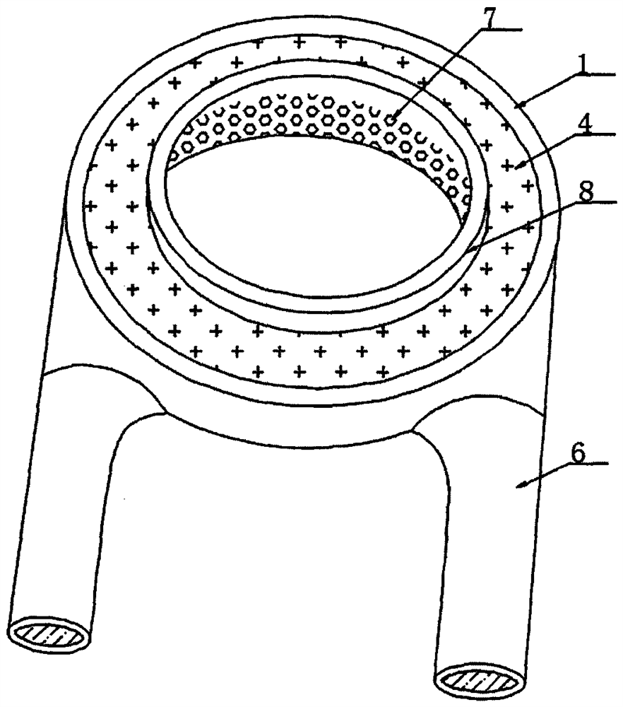
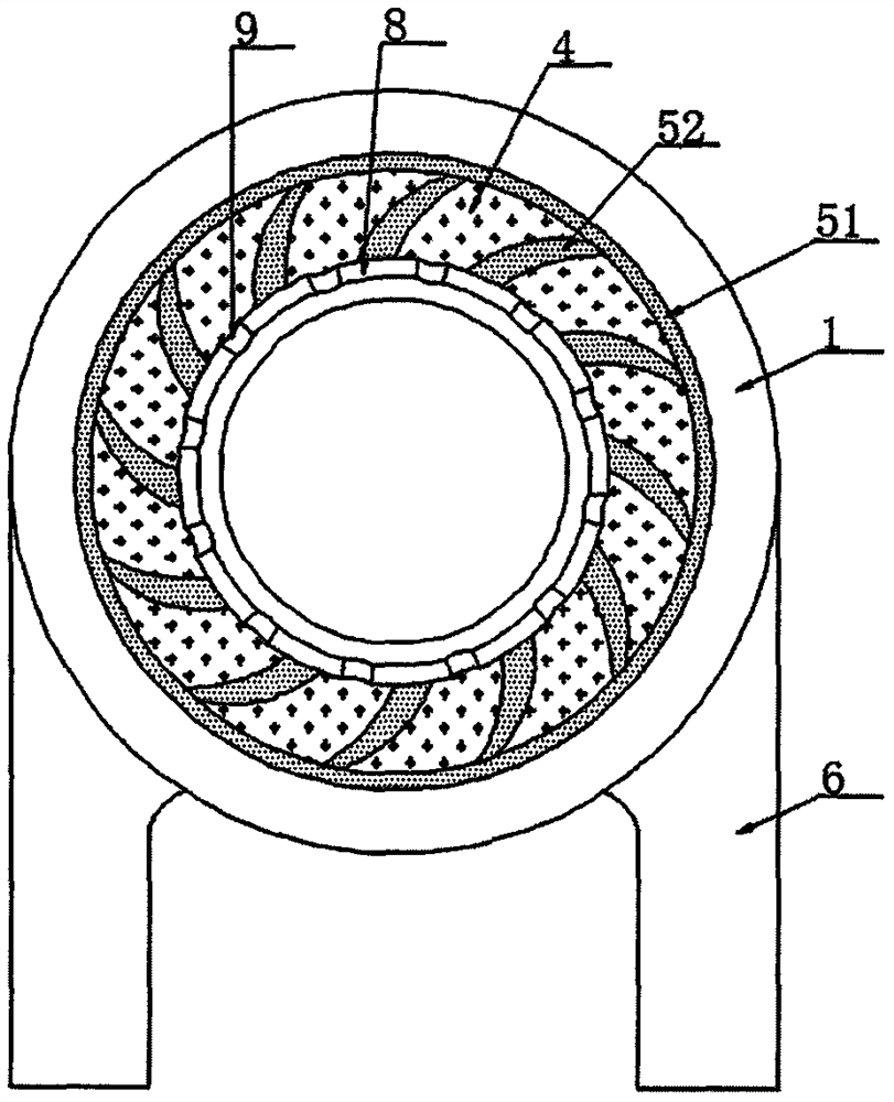
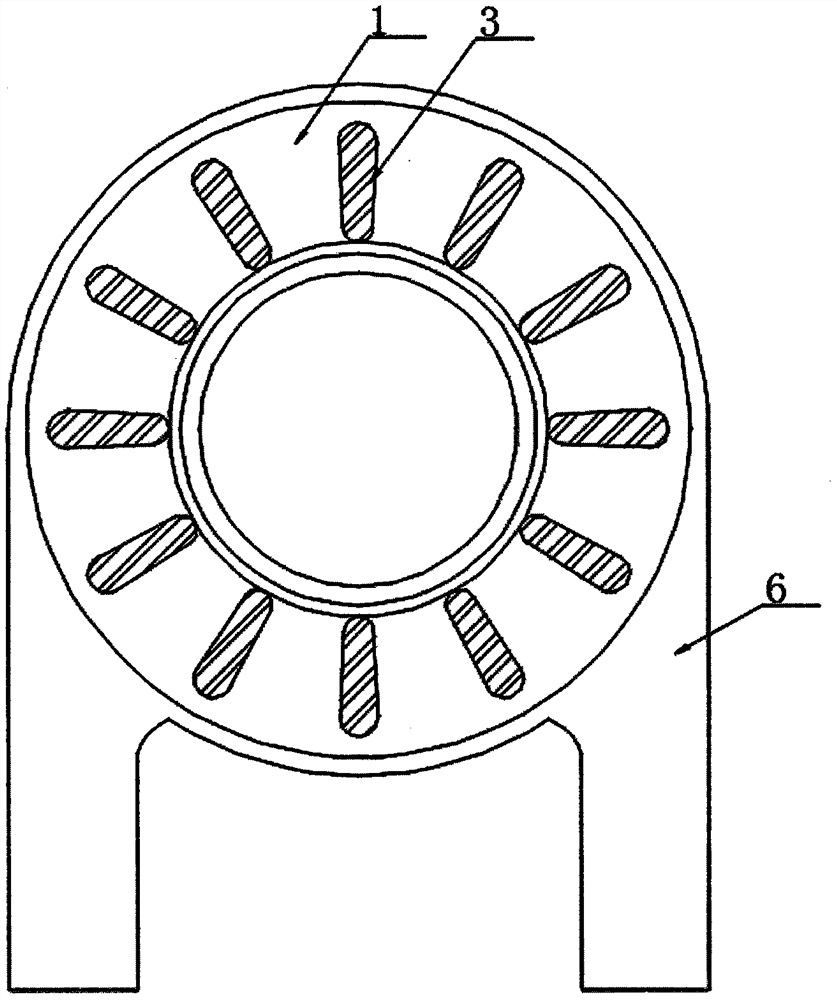
[0031] according to Figure 1-7 The coal-fired gasification ring shown includes a sealing steel ring 1, the interior of the sealing steel ring 1 is set as a cavity 2, the bottom of the sealing steel ring 1 is provided with a support plate 3, and the top of the sealing steel ring 1 is A placement groove 4 is provided, and a bearing frame 5 is movably connected in the placement groove 4. An air intake pipe 6 is provided on one side of the sealing steel ring 1, and an evenly distributed exhaust hole 7 is provided on the inner wall of the sealing steel ring 1. , the inner top of the sealing steel ring 1 is provided with a support flange 8, and the upper surface of the support flange 8 is provided with a channel 9;

[0032] The bottom of the support plate 3 is set as an inclined surface, and the surface of the support plate 3 is provided with anti-skid embossed lines;

[0033] An anti-slip layer is provided inside the placement groove 4, and the anti-slip layer is composed of seve...

Embodiment 2

[0046] according to Figure 1-7 The coal-fired gasification ring shown includes a sealing steel ring 1, the interior of the sealing steel ring 1 is set as a cavity 2, the bottom of the sealing steel ring 1 is provided with a support plate 3, and the top of the sealing steel ring 1 is A placement groove 4 is provided, and a bearing frame 5 is movably connected in the placement groove 4. An air intake pipe 6 is provided on one side of the sealing steel ring 1, and an evenly distributed exhaust hole 7 is provided on the inner wall of the sealing steel ring 1. , the inner top of the sealing steel ring 1 is provided with a support flange 8, and the upper surface of the support flange 8 is provided with a channel 9;

[0047]The inside of the cavity 2 is provided with a support rib, and the support rib is made of cast iron material;

[0048] The sealing steel ring 1 can be designed into various models according to the size, size and specifications of the gas furnace, such as single-...


PUM


Abstract

The invention discloses a fire coal gasification ring, and particularly relates to the field of gas furnace auxiliary equipment. The fire coal gasification ring comprises a sealing steel ring, whereina cavity is formed in the sealing steel ring, support plates are arranged at the bottom of the sealing steel ring, a placing groove is formed in the top of the sealing steel ring, a bearing frame ismovably connected in the placing groove, air inlet pipes are arranged on one side of the sealing steel ring, and exhaust holes are evenly distributed in the inner side wall of the sealing steel ring.According to the fire coal gasification ring, a good installation effect is achieved through the support plates and anti-skid protruding lines, the air inlet pipes enable air to enter, the air circulation amount is increased, oxygen needed by combustion is provided, secondary combustion of fire coal is promoted, the fire coal is fully combusted, the effective utilization efficiency of resources isimproved, no smoke is generated after the fire coal is fully combusted, and the environment-friendly effect can be achieved; and a supporting flange is matched with the bearing frame to effectively support a pot body, heat is exhausted from the exhaust holes and penetrates through a channel to fill the outer side of the bearing frame, and the heat energy utilization efficiency is improved.

Description

technical field [0001] The invention relates to the field of gas furnace auxiliary equipment, and more specifically, the invention relates to a coal-fired gasification circle. Background technique [0002] The gas furnace heats the pot body at the top during the combustion process. In order to make better use of heat energy, a rack is usually placed on the top of the gas furnace to allow the air to circulate normally. The coal-fired gasification ring is to improve the coal-fired heat utilization efficiency. [0003] In the existing coal-fired gasification circle structure, the air circulation effect is not good, and the oxygen cannot be fully combined, resulting in low efficiency of heat energy utilization, and also produces smoke and dust, polluting the environment. [0004] Therefore, it is necessary to invent a coal-fired gasification circle to solve the above problems. Contents of the invention [0005] In order to overcome the above-mentioned defects of the prior ar...

Claims


Application Information

Patent Timeline
IPC IPC(8): F24C3/00F24C15/10
CPCF24C3/008F24C15/101
Inventor 安金城
Owner 安金城
Why Eureka
Try Eureka