Terrestrial heat utilization system based on underground diaphragm walls and utilization method thereof

An underground continuous wall and geothermal technology, which is applied to the collectors and geothermal power generation using groundwater as a working fluid, can solve the problems of deep insertion depth, large cross-sectional area, low utilization rate, etc., and achieve great economy. , large energy, easy to use effect

Pending Publication Date: 2020-12-08
ZHEJIANG UNIV OF TECH
View PDF0 Cites 0 Cited by
  • Summary
  • Abstract
  • Description
  • Claims
  • Application Information

AI Technical Summary

Problems solved by technology

In some deep and large foundation pits, the underground diaphragm wall enclosure structure is deeply inserted into the soil, the cross-sectional area is large, and the cost is high, but the utilization rate of the underground permanent enclosure structure is low.

Method used


Image

  • Terrestrial heat utilization system based on underground diaphragm walls and utilization method thereof
  • Terrestrial heat utilization system based on underground diaphragm walls and utilization method thereof
  • Terrestrial heat utilization system based on underground diaphragm walls and utilization method thereof

Examples


Embodiment Construction

[0030] The technical solution of the patent of the present invention will be clearly and completely described below in conjunction with the accompanying drawings. Apparently, the described embodiments are part of the embodiments of the present invention, not all of them. Based on the embodiments of the present invention, all other embodiments obtained by persons of ordinary skill in the art without making creative efforts belong to the protection scope of the present invention.

[0031] In the description of the present invention, it should be noted that if the terms "center", "upper", "lower", "left", "right", "vertical", "horizontal", "inner", "outer" appear ” and other indicated orientations or positional relationships are based on the orientations or positional relationships shown in the accompanying drawings, which are only for the convenience of describing the present invention and simplifying the description, rather than indicating or implying that the referred device or...


PUM


Abstract

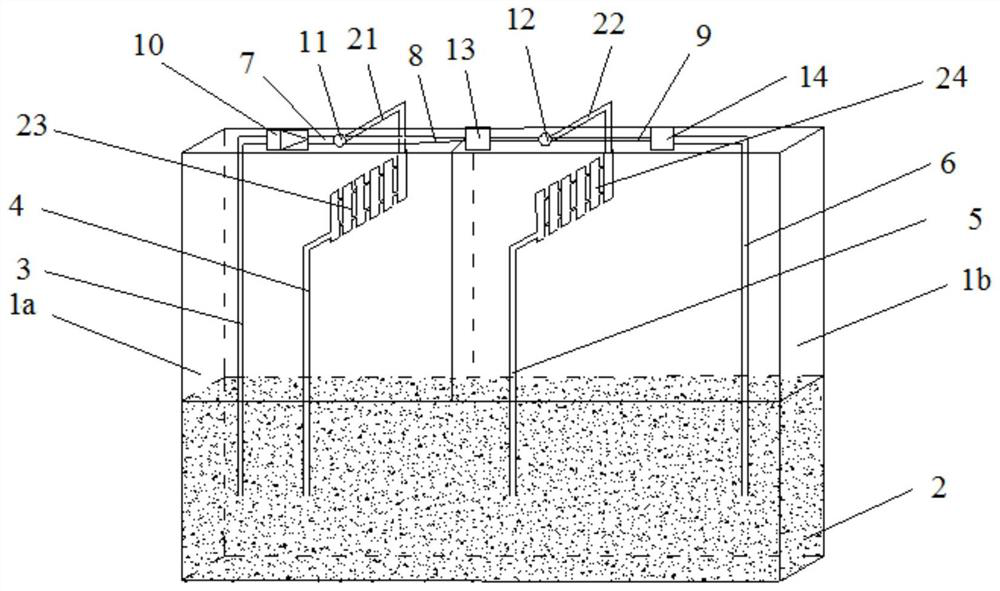
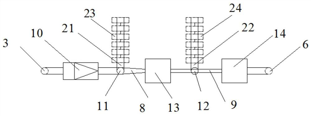
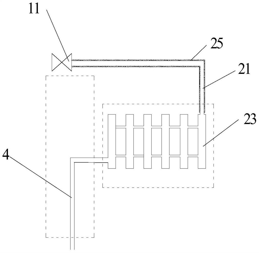
The invention provides a terrestrial heat utilization system based on underground diaphragm walls. The system comprises the first underground diaphragm wall, the second underground diaphragm wall andan underground water layer. A water input pipe and a first water output pipe are arranged on the first underground diaphragm wall. A second water output pipe and a third water output pipe are arrangedon the second underground diaphragm wall. The underground water layer communicates with a high-pressure water pump through the water input pipe. The water output end of the high-pressure water pump is sequentially connected with a first electric shunting type valve, a first high-pressure heat energy converter, a second electric shunting type valve, a second high-pressure heat energy converter andthe third water output pipe. The other water output end of the first electric shunting type valve is connected with the first water output pipe through a first grid type heat exchanger, and the otherwater output end of the second electric shunting type valve is connected with the second water output pipe through a second grid type heat exchanger. The invention further provides a utilization method of the geothermal utilization system based on the underground diaphragm walls. The system has the advantages of being large in energy, easy to utilize and the like, terrestrial heat is utilized reasonably, and thus benefits can be brought to economy and environment.

Description

technical field [0001] The invention relates to the technical field of geothermal utilization, in particular to a geothermal utilization system based on an underground continuous wall and a utilization method thereof. Background technique [0002] With the development of foundation pit engineering, more and more foundation pits tend to develop in deep, large and poor geological areas, and most of the foundation pit enclosure structures adopt reinforced concrete underground diaphragm walls. As the enclosure structure of the foundation pit, the underground diaphragm wall has the main advantages of good integrity, high rigidity, and good impermeability. In some deep and large foundation pits, the underground diaphragm wall enclosure structure has a deep insertion into the soil, a large cross-sectional area, and high cost, and its utilization rate is low only as an underground permanent enclosure structure. As a new type of renewable energy, geothermal energy is mainly stored b...

Claims


Application Information

Patent Timeline
Patent Type & Authority Applications(China)
IPC IPC(8): F24T10/20
CPCF24T10/20Y02E10/10
Inventor 胡敏云符东王捷张勇
Owner ZHEJIANG UNIV OF TECH
Why Eureka
Try Eureka