
Radar target tracking speed correction method and device

A radar target tracking and speed correction technology, applied in the radar field, can solve problems such as large deviations in the solution speed, and achieve the effects of improving accuracy, reducing the amount of calculation, and smoothly eliminating measurement errors

Pending Publication Date: 2020-12-08
BEIJING JINGWEI HIRAIN TECH CO INC
View PDF0 Cites 5 Cited by
  • Summary
  • Abstract
  • Description
  • Claims
  • Application Information

AI Technical Summary

Problems solved by technology

Another method is to use the position information of the front and rear frames of the target to perform difference or fitting to estimate the initial velocity vector of the target, but this method is only suitable for the laser radar with relatively accurate position measurement. For the radar with low position measurement accuracy, Direct use of position information to solve the speed is prone to large deviations

Method used


Image

  • Radar target tracking speed correction method and device
  • Radar target tracking speed correction method and device
  • Radar target tracking speed correction method and device

Examples


Embodiment Construction

[0065] The following will clearly and completely describe the technical solutions in the embodiments of the present invention with reference to the accompanying drawings in the embodiments of the present invention. Obviously, the described embodiments are only some, not all, embodiments of the present invention. Based on the embodiments of the present invention, all other embodiments obtained by persons of ordinary skill in the art without making creative efforts belong to the protection scope of the present invention.

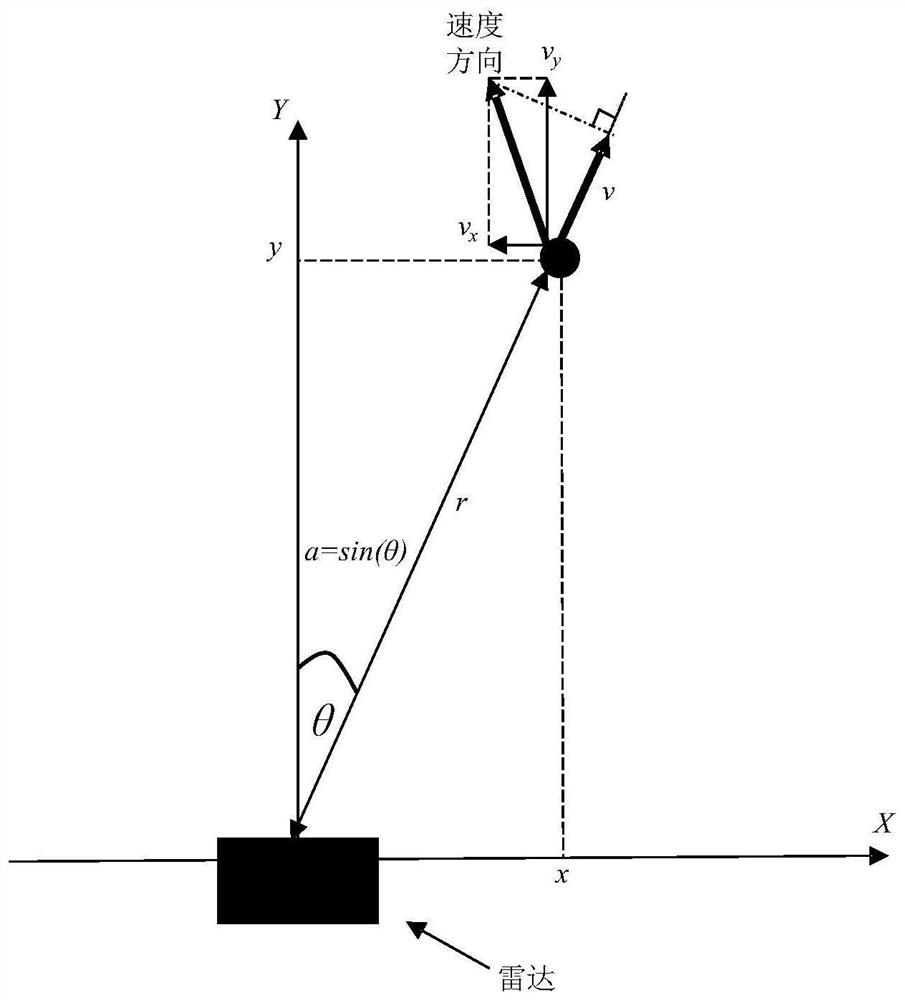
[0066] Such as figure 1 As shown, in the radar coordinate system, the measurement information of the target includes the slant distance r, the sine value of the azimuth angle a=sin(θ) and the Doppler velocity v. θ is the azimuth angle. The position coordinates of the target are (x, y), and the two-dimensional velocity vector of the target is (v x , v y ). Doppler velocity v=(v x *x+v y *y) / [(x*x+y*y)^(0.5)]).

[0067] see figure 2 , a radar target tra...


PUM


Abstract

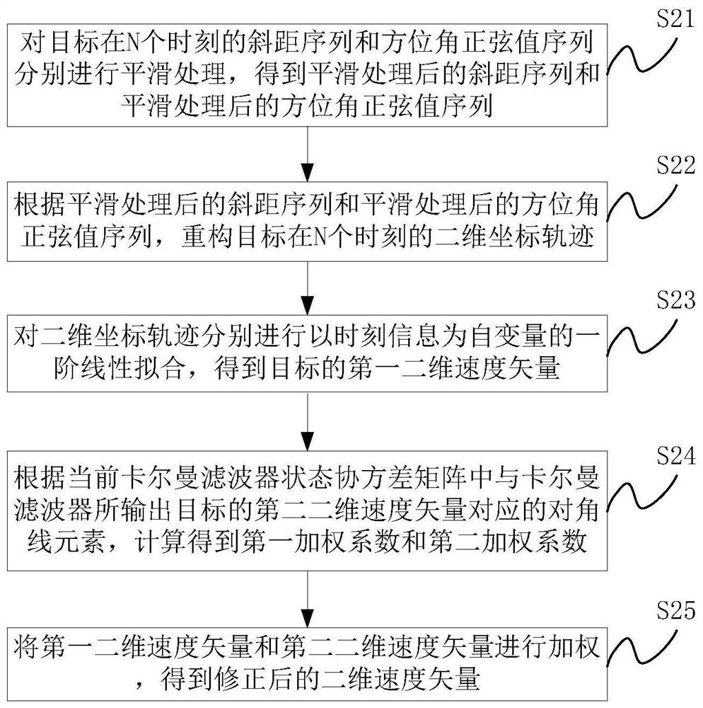
The invention provides a radar target tracking speed correction method and device, and the method comprises the steps: respectively carrying out the smoothing of a slope distance sequence and an azimuth sine value sequence of a target at N moments, and obtaining a smoothed slope distance sequence and a smoothed azimuth sine value sequence; reconstructing a two-dimensional coordinate track of the target according to the smoothed data; fitting the reconstructed two-dimensional coordinate track for obtaining a two-dimensional speed vector, and finally, setting a weighting coefficient of the two-dimensional velocity vector based on a Kalman filter state covariance matrix, and weighting the two-dimensional velocity vector of the Kalman filter output target and the two-dimensional velocity vector obtained by first-order linear fitting, and obtaining a corrected two-dimensional velocity vector. The measurement error of each piece of measurement information is smoothly eliminated, so that thespeed estimation precision is improved; and search operation or iterative matrix operation and the like do not need to be executed in the calculation process, so that the operand is reduced.

Description

technical field [0001] The invention relates to the technical field of radar, and more specifically, to a method and device for correcting radar target tracking speed. Background technique [0002] The continuous tracking of the target by radar is usually solved by establishing the motion state transition model at the previous moment and the current moment, combined with the target information measured by the radar at the current moment, and using the extended Kalman filter, unscented Kalman filter, etc. . This type of tracking method does not have an earlier track as input at the beginning of the track, and cannot use the tracker for filtering. It can only forcefully define an initial motion state, and substitute this state into the tracker as the second tracking cycle input of. The radar can calculate the two-dimensional position coordinates of the target through the measured value of the slant range and the sine value of the azimuth angle, but it cannot calculate the tw...

Claims


Application Information

Patent Timeline
Patent Type & Authority Applications(China)
IPC IPC(8): G01S13/72
CPCG01S13/723
Inventor 刘长江李坤乾张学健石志轩
Owner BEIJING JINGWEI HIRAIN TECH CO INC
Learn More