A kind of optical cone grinding and polishing device and method

A polishing device and cone technology, which is applied to optical surface grinders, grinding/polishing equipment, surface polishing machine tools, etc., can solve the problems that the processing level of components cannot meet the high-precision comprehensive indicators, and is not suitable for conical surface polishing, etc. Consistency, increase service life, and ensure the effect of uniformity

Active Publication Date: 2022-02-18
LASER FUSION RES CENT CHINA ACAD OF ENG PHYSICS
View PDF10 Cites 0 Cited by
  • Summary
  • Abstract
  • Description
  • Claims
  • Application Information

AI Technical Summary

Problems solved by technology

[0002] Lasers used in aviation, aerospace, military defense and other fields have the demand for miniaturization and light weight, leading to major changes in the principle and structure of lasers. Therefore, a large number of heterogeneous optical elements are required in the design of lasers. Special optical properties are used more and more. In the application environment of high-energy laser, in order to ensure the quality of laser beam, the components are required to have extremely high mechanical precision and optical index requirements. The existing planar, spherical or aspherical The processing principle and method are not suitable for the polishing of the conical surface, especially the realization of the extremely high optical processing index of the conical surface. There is little research in China, and the processing level of the components cannot meet the needs of high-precision comprehensive indicators.

Method used


Image

  • A kind of optical cone grinding and polishing device and method
  • A kind of optical cone grinding and polishing device and method
  • A kind of optical cone grinding and polishing device and method

Examples


Embodiment 1

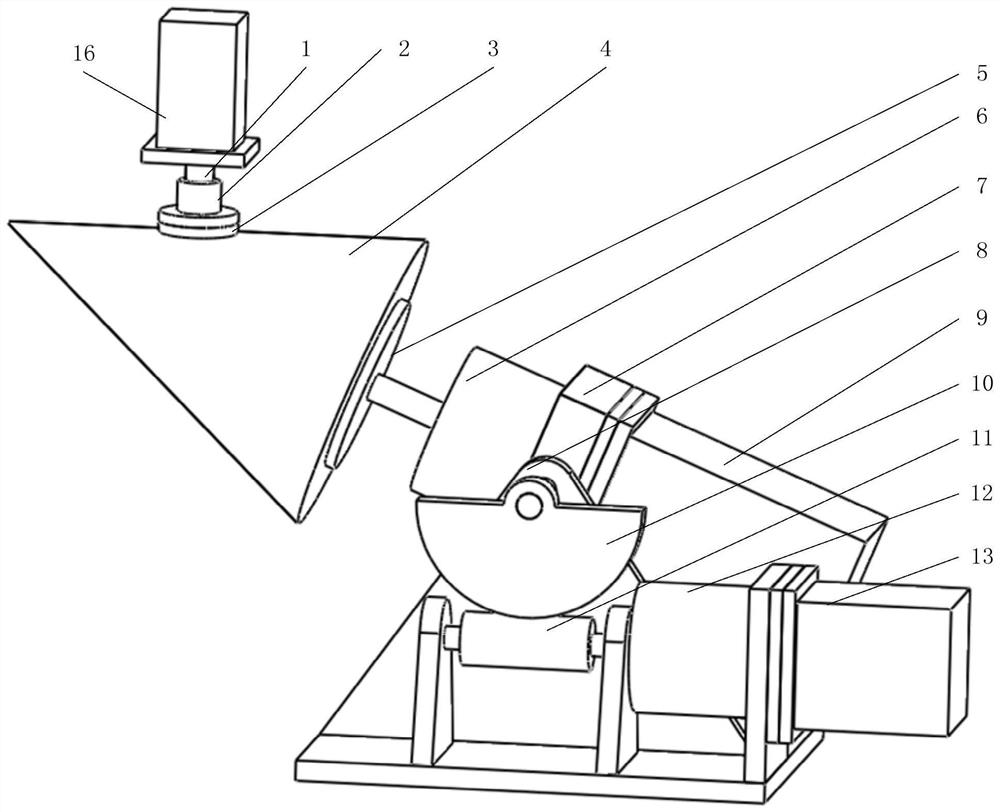
[0044] This embodiment discloses an optical conical grinding and polishing device, see attached figure 1 , which includes a support frame 8, a movable mechanism, a thimble 1, a flat polishing disc 2, and a polishing disc motor 16; the movable mechanism is installed on the support frame 8, and the movable mechanism has two degrees of freedom of movement: the first degree of freedom of end rotation, And the second degree of freedom that the center of rotation is perpendicular to the rotation axis of the end; the end of the movable mechanism is used to connect the cone to be processed; the thimble 1 is located in the plane where the rotation axis of the end of the movable mechanism moves in the second degree of freedom; the plane The polishing disc 2 is universally connected with the thimble 1 , the thimble 1 is driven by the polishing disc motor 16 , and the surface of the flat polishing disc 2 is provided with a polishing material layer 3 .

[0045] For specific implementation,...

Embodiment 2

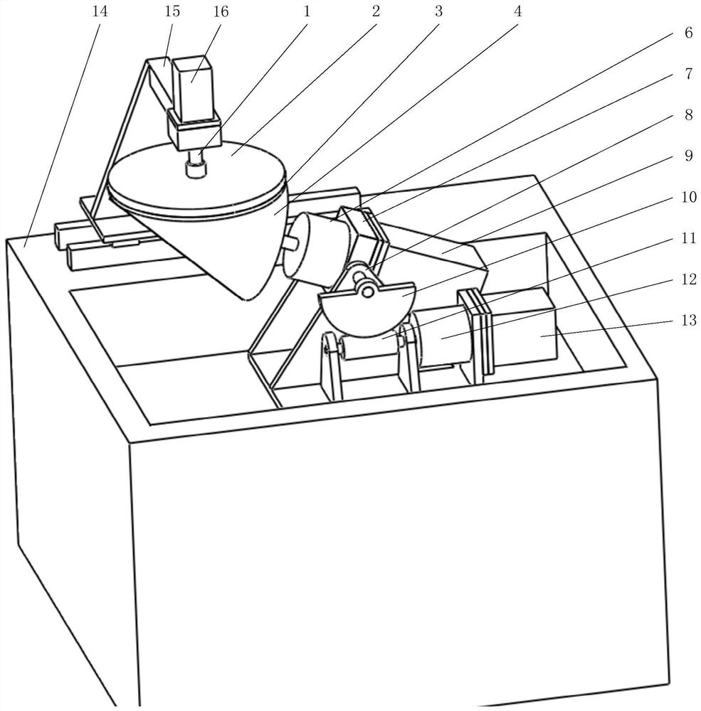
[0077] This embodiment discloses a grinding and polishing machine tool, such as figure 2 As shown, it includes a frame 14 and a kind of optical cone grinding and polishing device in the above-mentioned embodiment, the support frame 8 of the optical cone grinding and polishing device is installed on the frame 14, and the frame 14 is also provided with a polishing disk motor mounting shaft 15. The polishing disc motor 16 of the optical conical grinding and polishing device is installed on the polishing disc motor installation shaft 15. Obviously, the position of the polishing disk motor installation shaft 15 needs to correspond to the position of the installation support frame 8, so that finally the thimble 1 corresponds to the output shaft of the axial drive mechanism (ie, the shaft end of the movable mechanism).

[0078]In one embodiment, the frame is a single-axis grinding and polishing machine frame, and the mounting shaft of the polishing disc motor is a swing shaft struct...

Embodiment 3

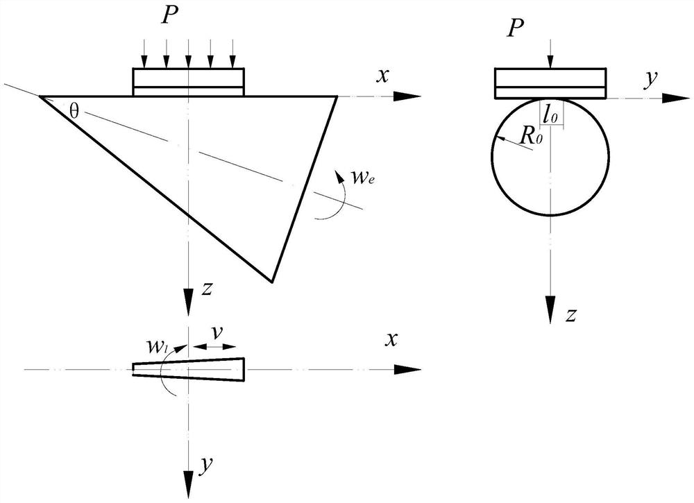
[0081] In an implementation example, such as figure 2 , for the case that the frame is a single-axis grinding and polishing machine frame, a method of fast polishing is designed by using the method of full-diameter polishing (the size of the polishing disc is equivalent to the size of the processed component), and the polishing disc is on the polishing disc. While rotating under the drive of the motor, it swings back and forth along the x-axis driven by the motor installation shaft (15). The swing center can be adjusted on the frame. The components rotate under the drive of the drive motor (16). The position, swing amplitude, speed, and component rotation speed realize component polishing and surface shape maintenance.

[0082] In another implementation example, for the case where the frame is a three-axis CNC machine tool, a method of precision modification control is designed by using sub-aperture polishing (the size of the polishing disc is much smaller than the size of th...


PUM


Abstract

The invention belongs to the field of optical device processing, and discloses an optical cone grinding and polishing device and method. The device includes a support frame, a movable mechanism, a thimble, a flat polishing disc and a polishing disc motor; the movable mechanism is installed on the support frame, and the movable mechanism has two degrees of freedom of movement: the first degree of freedom of the end rotation, and the rotation center and the end The second degree of freedom perpendicular to the rotation axis; the end of the movable mechanism is used to connect the cone to be processed; the thimble is located in the plane where the rotation axis at the end of the movable mechanism moves in the second degree of freedom; the flat polishing disc is universally connected with the thimble The thimble is connected to the motor shaft of the polishing disc, and a polishing material layer is arranged on the surface of the flat polishing disc. Connect the cone to the shaft end of the movable mechanism, adjust the contour line of the cone to the level, and polish it with a helical trajectory around the axis of the cone. , swing speed and amplitude control.

Description

technical field [0001] The invention relates to the field of optical device processing, in particular to an optical cone grinding and polishing device and a polishing method. Background technique [0002] Lasers used in aviation, aerospace, military defense and other fields have the demand for miniaturization and light weight, leading to major changes in the principle and structure of lasers. Therefore, a large number of heterogeneous optical elements are required in the design of lasers. Special optical properties are used more and more. In the application environment of high-energy laser, in order to ensure the quality of laser beam, the components are required to have extremely high mechanical precision and optical index requirements. The existing planar, spherical or aspherical The processing principles and methods are not suitable for the polishing of the conical surface, especially the realization of the extremely high optical processing index of the conical surface. T...

Claims


Application Information

Patent Timeline
Patent Type & Authority Patents(China)
IPC IPC(8): B24B13/00B24B5/14B24B29/04B24B49/00B24B45/00
CPCB24B13/00B24B5/14B24B29/04B24B49/006B24B45/003
Inventor 鲍振军杨李茗朱衡李智钢蔡红梅崔建朋周衡
Owner LASER FUSION RES CENT CHINA ACAD OF ENG PHYSICS
Why Eureka
Try Eureka