Automatic ceramic bowl blank forming machine

A technology of automatic molding machine and molding mechanism, which is applied in ceramic molding machines, ceramic molding workshops, auxiliary molding equipment, etc. It can solve the problems of unguaranteed quality, untimely supply, and low production efficiency, so as to improve efficiency and avoid defects , Guarantee the effect of quality

Inactive Publication Date: 2020-12-11
王艳伟
View PDF9 Cites 10 Cited by
  • Summary
  • Abstract
  • Description
  • Claims
  • Application Information

AI Technical Summary

Problems solved by technology

[0005] In order to overcome the shortcomings of testing the skill of the master, the production quality cannot be guaranteed, the production efficiency is also very low, and the bowl cannot be supplied in time when the bowl is urgently needed, the technical problem to be solved: provide a universally applicable guarantee for a certain production quality At the same time, the production efficiency is improved, and the ceramic bowl blank automatic forming machine that can realize mass production

Method used


Image

  • Automatic ceramic bowl blank forming machine
  • Automatic ceramic bowl blank forming machine
  • Automatic ceramic bowl blank forming machine

Examples


Embodiment 1

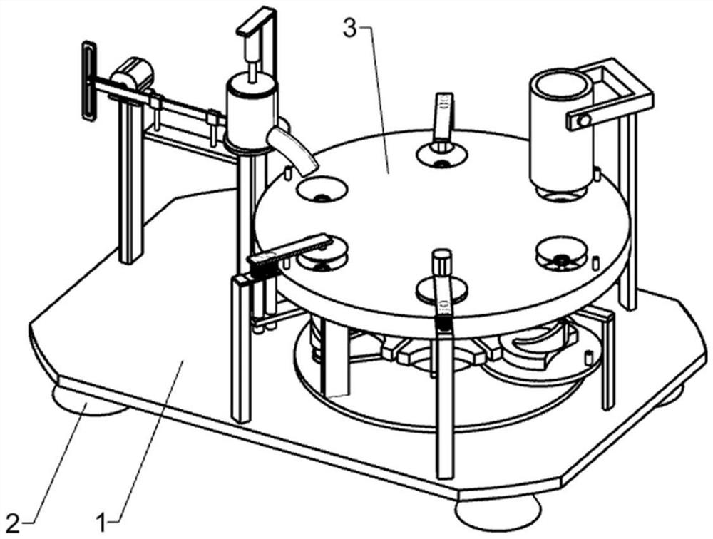
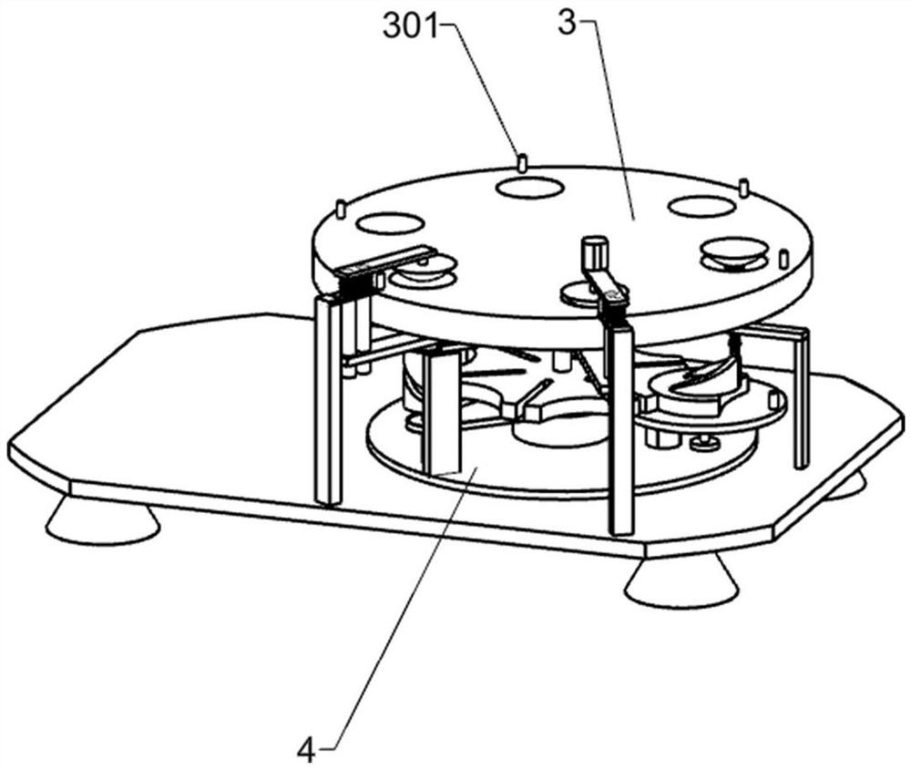
[0034] A kind of ceramic bowl blank automatic forming machine, such as Figure 1-3 As shown, it includes a bottom plate 1, a support block 2, a worktable 3, a retaining column 301, a support plate 4, a support column 5, a support platform 6, an intermittent mechanism, a forming mechanism, an edge scraping mechanism, an ejection mechanism, and a mold sending mechanism. Inlet mechanism, adjustment mechanism and feeding mechanism, four support blocks 2 are symmetrically fixed under the base plate 1, a support plate 4 is fixedly connected to the upper right side of the base plate 1, and a support platform 6 is fixedly connected to the middle position of the upper part of the support plate 4. The column 5 is rotatably installed vertically in the support platform 1 6, the upper side of the support column 5 is fixedly connected to the workbench 3, and the workbench 3 is arranged horizontally on the bottom plate 1, and six retaining columns 301 are fixedly arranged in an array on the w...

Embodiment 2

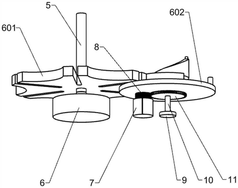
[0037] On the basis of Example 1, such as Figure 3-9 As shown, the intermittent mechanism includes an intermittent disc 601, a dial 602, a motor one 7, a spur gear one 8, a support table two 9, a pole one 10 and a spur gear two 11, and the intermittent disc 601 is fixed on the support column 5 close to The lower side of the support platform one 6, the support platform two 9 is installed on the support plate one 4, the support platform two 9 is positioned at the right side of the support platform one 6, and the support platform two 9 is rotationally connected with a pole one 10, and the pole one 10 A dial 602 is fixedly connected to the upper end of the dial 602, and the notched disc and cylindrical block on the dial 602 cooperate with the arc groove and the slot on the intermittent disc 601 respectively, and the spur gear 11 is fixed on the upper side of the pole 10 , the spur gear two 11 is below the dial 602, the motor one 7 is fixedly connected on the support plate one 4 n...

Embodiment 3

[0046] On the basis of Example 2, such as Figure 10-13As shown, the mold feeding mechanism includes support rod six 29, U-shaped rod 2901, cylindrical rod four 2902, storage bucket 30, baffle plate 1 3001, baffle plate 2 3002, shaft rod 1 3003, sector gear 1 3004, shaft rod 2 3005, sector gear 2 3006, retaining ring 1 3007 and retaining ring 2 3008, strut 6 29 is affixed to the upper right side of base plate 1, and the upper end of strut 6 29 away from base plate 1 is affixed with U-shaped bar 2901, U Two cylindrical rods 2902 are fixedly connected to the left side of the type rod 2901 away from the support rod 6 29, the storage bucket 30 is fixedly connected with the cylindrical rod 2902, and the lower side of the storage bucket 30 close to the workbench 3 is connected with a shaft rod 1 3003 for rotation and the second shaft 3005, the first baffle 3001 is slidingly connected with the retaining column 301, the middle part of the first baffle 3001 is fixedly connected to the ...


PUM


Abstract

The invention relates to a forming machine, in particular to an automatic ceramic bowl blank forming machine. The technical problem to be solved is to provide a universally-applicable automatic ceramic bowl blank forming machine which improves the production efficiency and can realize batch production while ensuring the certain production quality. The automatic ceramic bowl blank forming machine is characterized in that the automatic ceramic bowl blank forming machine comprises a bottom plate, supporting blocks, a workbench, blocking columns, a first supporting plate, a supporting column, an intermittent mechanism, a forming mechanism, an edge scraping mechanism, an ejection mechanism, a mold feeding-in mechanism and the like, wherein the multiple supporting blocks are distributed on one side of the bottom plate in an array mode, the first supporting plate is fixedly connected to the side, away from the supporting blocks, of the bottom plate, a first supporting table is fixedly connected to the first supporting plate, and the supporting column is rotatably connected to the first supporting table. The automatic ceramic bowl blank forming machine structurally adopts bowl-shaped moldblocks, uniform specifications are provided for the bowl shape, and the automatic ceramic bowl blank forming machine can be universally suitable for bowl making devices.

Description

technical field [0001] The invention relates to a forming machine, in particular to an automatic ceramic bowl blank forming machine. Background technique [0002] Bowls are a common eating tool in people's lives. Every household is inseparable from bowls. Everyone uses at least one bowl to eat. Therefore, there is a great demand for bowls in society. [0003] In the traditional production process, the mud is usually manually thrown in the center of the turntable of the potter's wheel, and the general shape of the green body is drawn out with the flexion and extension of the hand. Cover the half-dried billet on the mold, press the outer wall of the billet evenly, and then demould, put the billet on the sharp barrel of the potter's wheel, turn the wheel, and turn it with a knife to make the billet thickness appropriate. The outside and inside are smooth, and finally the processed billets are placed on a wooden rack to dry. This kind of craftsmanship is a test of the master's ...

Claims


Application Information

Patent Timeline
IPC IPC(8): B28B15/00B28B5/06B28B13/02B28B13/06B28B17/00
CPCB28B5/06B28B13/0215B28B13/0295B28B13/065B28B15/00B28B17/00
Inventor 王艳伟
Owner 王艳伟
Why Eureka
Try Eureka