Cable take-up and pay-off device for power field

A retractable device and technology in the field, applied in the field of power cables, can solve problems affecting cable storage and use quality, and consume manpower and material resources, and achieve the effects of dry and clean storage environment, prolonging service life, and reducing labor intensity

Inactive Publication Date: 2020-12-11
包丽丽
View PDF1 Cites 3 Cited by
  • Summary
  • Abstract
  • Description
  • Claims
  • Application Information

AI Technical Summary

Problems solved by technology

However, when the device is wound, people need to artificially clean the sludge and sewage on the surface of the power cable, which consumes a lot of manpower and material resources. If it is not cleaned, the storage and use quality of the cable will be greatly affected.

Method used


Image

  • Cable take-up and pay-off device for power field
  • Cable take-up and pay-off device for power field
  • Cable take-up and pay-off device for power field

Examples


Embodiment 1

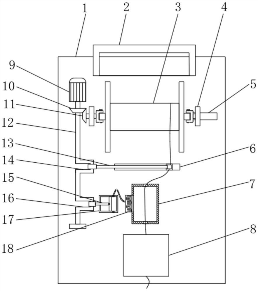
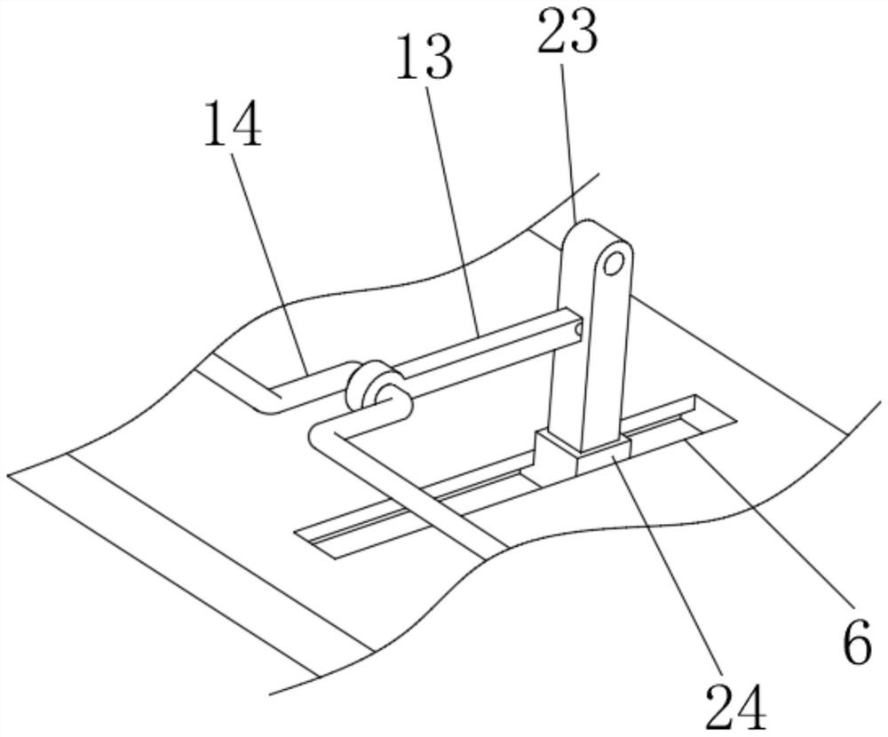
[0026] Embodiment one: refer to Figure 1~4 , in an embodiment of the present invention, a cable retracting device for the electric power field includes a base 1, a motor 9 is placed near the rear end of the base 1 to provide a power source, and the output end of the motor 9 is connected to a transmission shaft 12, One end of the transmission shaft 12 close to the motor 9 is connected with a driving bevel gear 10, and the driving bevel gear 10 is meshed with a driven bevel gear 11, and the output shaft end of the driven bevel gear 11 is provided with a winding reel 3 to realize the power cable. Winding, one end of the drive shaft 12 away from the motor 9 is connected with a first crankshaft 14 and a second crankshaft 16, the first crankshaft 14 is rotatably connected with a crank rod 13, and the crank rod 13 is rotatably connected with a guide column 23, and the guide The lower end of the column 23 is fixedly connected with a guide slider 24, and the guide slider 24 is moved a...

Embodiment 2

[0035] Embodiment 2: This invention also provides another embodiment, which is improved on the basis of the above embodiment, and one end of the winding reel 3 away from the driven bevel gear 11 is connected to the column 4, The column 4 is movable and connected in the moving slot 5 provided on the surface of the base 1, which is convenient for adjusting the position of the column 4 at the right end, and is suitable for winding reels 3 of different lengths, with good flexibility.

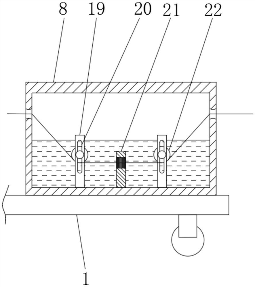
[0036] In summary, when the invention is working, according to the length of the winding reel 3, the fixed and clamping of different winding reels 3 can be realized by adjusting the column 4 on the right side to move along the moving groove 5. The power cable passes through the cleaning box 8, the drying box 7, and the through holes of the guide column 23 to be wound up on the winding reel 3, the motor 9 is turned on, and the driving bevel gear 10 meshes with the driven bevel gear 11 to realize the r...


PUM


Abstract

The invention discloses a cable take-up and pay-off device for the power field, and relates to the technical field of power cables. The cable take-up and pay-off device comprises a base, a motor is arranged at the position close to the rear end of the base, a transmission shaft is connected to the output end of the motor, a driving bevel gear is connected to the end, close to the motor, of the transmission shaft, and a driven bevel gear is in meshing transmission with the driving bevel gear. A winding disc is arranged at the output shaft end of the driven bevel gear, a first crankshaft and a second crankshaft are connected to the end away from the motor of the transmission shaft, the first crankshaft is rotationally connected with a crank rod, the crank rod is rotationally connected with aguide column, and a guide sliding block is fixedly connected to the lower end of the guide column. A stand column on the right side is adjusted to fix the winding disc with different lengths, at themoment, a power cable sequentially penetrates through a cleaning box, a drying box and through holes of the guide column to be wound on the winding disc, manual operation is not needed, labor intensity is reduced, cleaning and winding are achieved at the same time, work efficiency and work quality are greatly improved, and the storage environment of the power cable is fully guaranteed to be dry and clean.

Description

technical field [0001] The invention relates to the technical field of power cables, in particular to a cable retracting device for the electric power field. Background technique [0002] Electricity is an energy source powered by electrical energy. Invented in the 1870s, the invention and application of electricity set off the second industrialization climax. It has become one of the three scientific and technological revolutions in the world since the 18th century in human history. Since then, technology has changed people's lives. The large-scale power system that appeared in the 20th century is one of the most important achievements in the history of human engineering science. It is a power production and consumption system composed of power generation, power transmission, power transformation, power distribution and power consumption. It converts the primary energy of nature into electricity through mechanical energy devices, and then supplies electricity to various u...

Claims


Application Information

Patent Timeline
Patent Type & Authority Applications(China)
IPC IPC(8): B65H75/38B65H75/44
CPCB65H75/38B65H75/44B65H75/4481B65H2701/34
Inventor 包丽丽
Owner 包丽丽
Why Eureka
Try Eureka