Asphalt paving device for road construction

A laying device and road construction technology, applied in the direction of roads, roads, road repairs, etc., can solve the problems of low mixing effect, increased production costs, and decline in the quality of asphalt pavement, so as to facilitate mixing and laying evenly, avoid temperature drop, reduce The effect of production costs

Inactive Publication Date: 2020-12-11
李景明
View PDF0 Cites 13 Cited by
  • Summary
  • Abstract
  • Description
  • Claims
  • Application Information

AI Technical Summary

Problems solved by technology

[0003] Asphalt is solid at room temperature, and it needs to be heated to melt the solid asphalt during use. The heating temperature is generally 120 degrees. The asphalt heating in the prior art is generally heated by a boiler, and then transported to the laying equipment, which leads to asphalt The temperature drops, the mixing effect is low, the quality of the paved asphalt pavement is reduced, and there are often residual asphalt left on the inner wall of the paving equipment, which increases the production cost. Therefore, in view of the above current situation, it is urgent to develop a kind of road construction. device to overcome the deficiencies in current practical applications

Method used


Image

  • Asphalt paving device for road construction
  • Asphalt paving device for road construction
  • Asphalt paving device for road construction

Examples


Embodiment 1

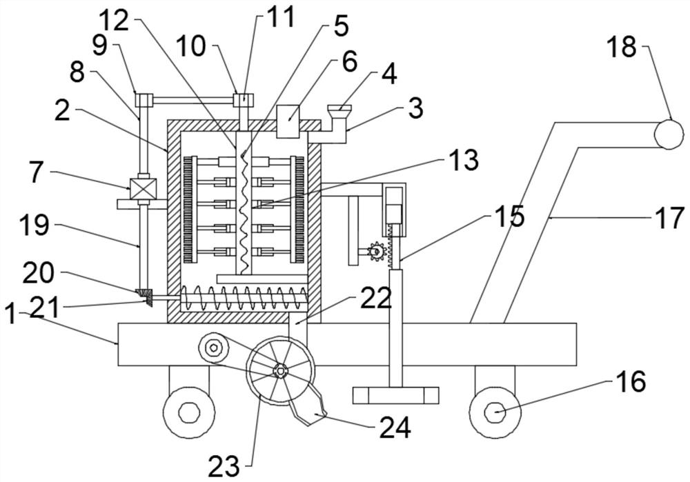
[0023] see Figure 1-2 , in an embodiment of the present invention, an asphalt paving device for road construction, comprising a base plate 1, a tank body 2 is arranged on the upper surface of the base plate 1, and the tank body 2 is divided into an inner layer and an outer layer, and the inner layer and the outer layer A water inlet pipe 3 is arranged between the outer layers, and a water inlet funnel 4 is arranged at the top of the water inlet pipe 3, and a sealing end cover is arranged on the water inlet funnel 4, and a feed inlet 6 is arranged at the top of the tank body 2, so that The outer surface of the left side of the tank body 2 is fixedly connected with a first installation frame, and the upper surface of the first installation frame is provided with a biaxial motor 7, and one end of the biaxial motor 7 is fixedly connected with a rotating shaft 8 through a coupling, so The top end of the rotating shaft 8 is sleeved with a first transmission wheel 9, and the first t...

Embodiment 2

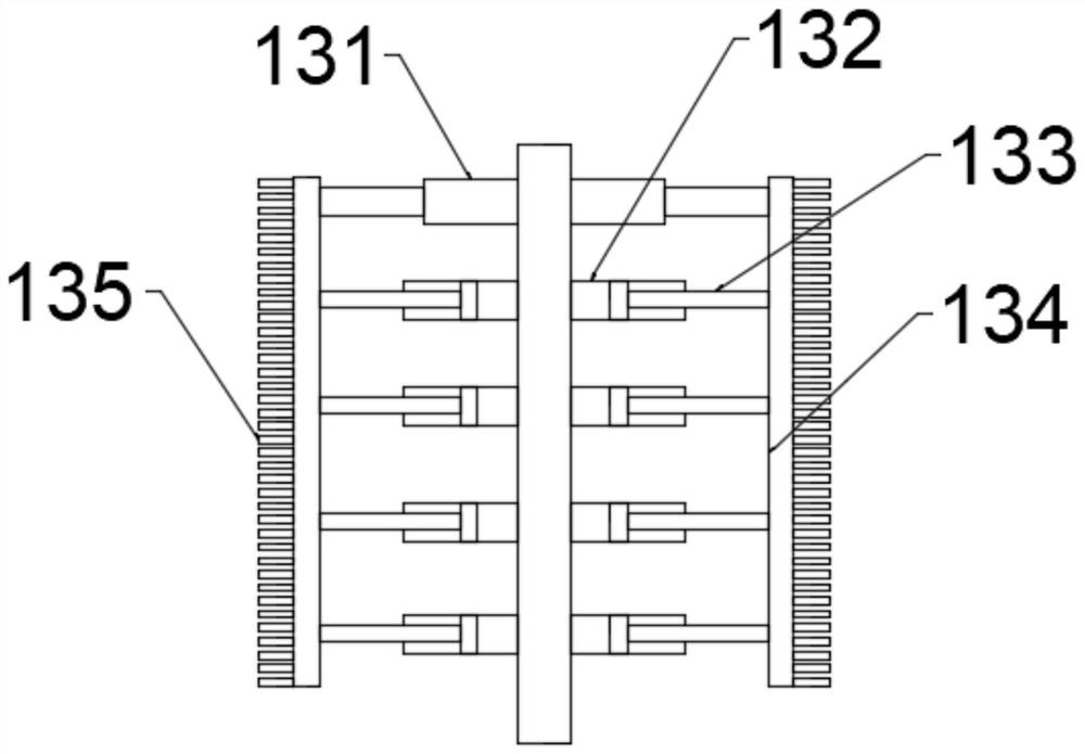
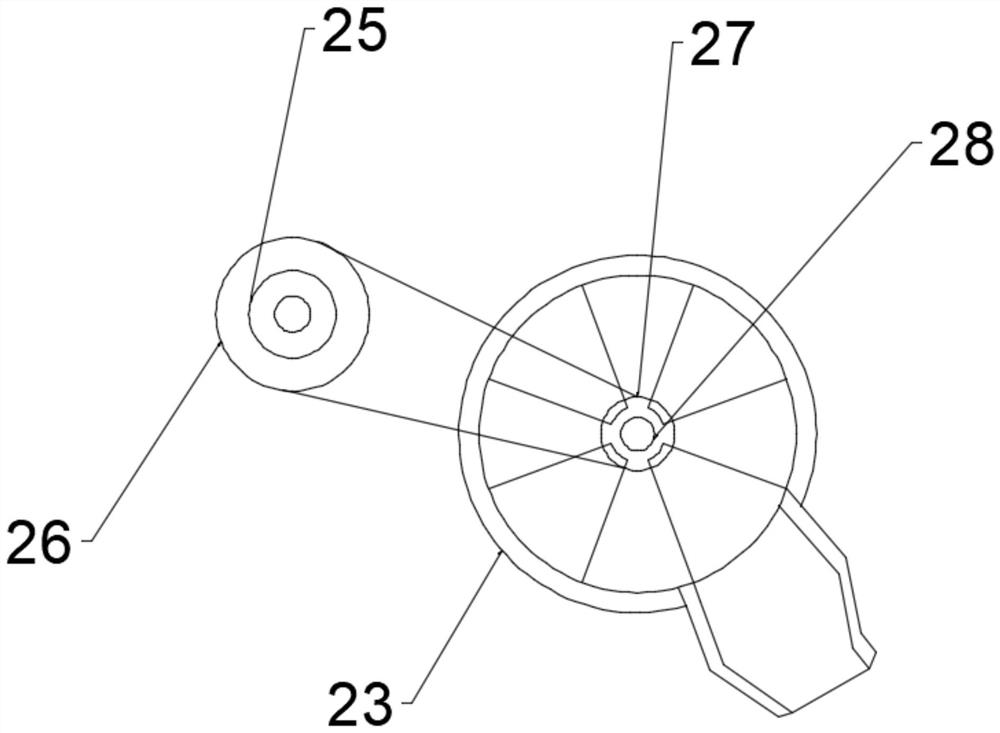
[0027] see Figure 1-4 , in this embodiment, one end of the biaxial motor 7 is fixedly connected with a first rotating shaft 19 through a coupling, and one end of the first rotating shaft 19 is sleeved with the driving bevel gear 20, and one end of the driving bevel gear 20 is meshed with a slave The driven bevel gear 21, one end of the driven bevel gear 21 is fixedly connected with the delivery device 14, the delivery device 14 includes a screw rod 141, the screw rod 141 is provided with a helical blade, and the tank body below the screw rod 141 2 The bottom end is provided with a discharge port 22, and the outlet of the discharge port 22 is provided with a fan-shaped rotating plate 23, and a discharge funnel 24 is provided below the fan-shaped rotating plate 23, and the fan-shaped rotating plate 23 is driven to rotate by a driving mechanism , the biaxial motor 7 drives the first rotating shaft 19 to rotate, and by driving the driving bevel gear 20 to mesh with the driven bev...


PUM


Abstract

The invention relates to the technical field of road paving, in particular to an asphalt paving device for road construction which comprises a bottom plate. A tank body is arranged on the upper surface of the bottom plate, the tank body is divided into an inner layer and an outer layer, a water inlet pipe is arranged between the inner layer and the outer layer, a water inlet funnel is arranged atthe top end of the water inlet pipe, and a sealing end cover is arranged on the water inlet funnel. A feeding port is formed in the top end of the tank body, a first mounting frame is fixedly connected to the outer surface of the left side of the tank body, a double-shaft motor is arranged on the upper surface of the first mounting frame, one end of the double-shaft motor is fixedly connected witha rotating shaft through a coupler, and the top end of the rotating shaft is sleeved with a first transmission wheel. The first transmission wheel is in transmission connection with a second transmission wheel through a transmission belt, and a rotating rod is fixedly connected with an inner cavity of the second transmission wheel. According to the asphalt paving device for road construction, byarranging an electric heating wire, the water inlet funnel and a stirring assembly, asphalt can be kept in a fluid state, the stirring effect is improved, and paving is convenient.

Description

technical field [0001] The invention relates to the technical field of road paving, in particular to an asphalt paving device for road construction. Background technique [0002] Asphalt is mainly used as a binder for paving roads and roofing materials. It is obtained by regular vacuum distillation of crude oil with appropriate properties, or it can also be obtained after vacuum residue oil is subjected to shallow oxidation or propane deasphalting process. It can also be obtained by using It is prepared by blending asphalt with different ductility and penetration grades. [0003] Asphalt is solid at room temperature, and it needs to be heated to melt the solid asphalt during use. The heating temperature is generally 120 degrees. The asphalt heating in the prior art is generally heated by a boiler, and then transported to the laying equipment, which leads to asphalt The temperature drops, the mixing effect is low, the quality of the paved asphalt pavement is reduced, and the...

Claims


Application Information

Patent Timeline
Patent Type & Authority Applications(China)
IPC IPC(8): E01C19/46
CPCE01C19/463
Inventor 李景明
Owner 李景明
Why Eureka
Try Eureka