
Intelligent sampling device for tunnel

A sampling device and intelligent technology, applied in the direction of sampling devices, supporting devices, drilling equipment, etc., can solve the problems of high labor intensity, reduce safety risks, and health impacts of workers, and achieve the goals of reducing safety risks, using convenience, and reducing impacts Effect

Pending Publication Date: 2020-12-11
XIHUA UNIV
View PDF0 Cites 3 Cited by
  • Summary
  • Abstract
  • Description
  • Claims
  • Application Information

AI Technical Summary

Problems solved by technology

[0004] In order to overcome the disadvantages of inconvenient operation, high labor intensity and impact on health due to the use of manual hand-held sampling drills for sampling at the top of existing tunnels, the present invention provides an easy-to-use tool that can be pushed by hand, etc. In the application, the operator does not need to climb up to work, and the operator can control the sampling drill to rise or fall, turn left or backward through the remote control on the ground, and measure different heights and positions at the top of the curved tunnel. Carry out non-manual sampling operations, and can sample the side wall of the tunnel as needed, and control the drilling and withdrawal of the sampling drill bit during sampling, which brings convenience to the operator, reduces safety risks, and reduces dust A Tunnel Intelligent Sampling Device That Affects the Health of Operators

Method used


Image

  • Intelligent sampling device for tunnel
  • Intelligent sampling device for tunnel
  • Intelligent sampling device for tunnel

Examples


Embodiment Construction

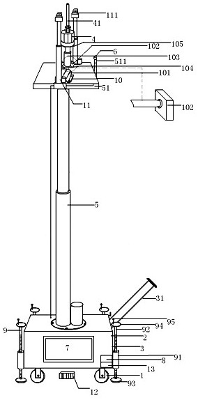
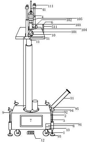
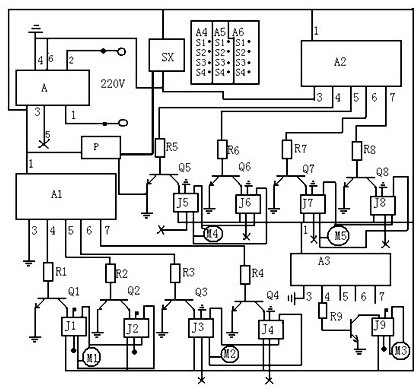
[0018] figure 1 , 2 As shown, a tunnel intelligent sampling device includes a mobile trolley 3 with four wheels 1, a rectangular box 2, an electric sampling drill body 4, an electro-hydraulic push rod 5, a camera 6, a display screen 7, and a stabilized power supply 8. An "n" type handle 31 is welded on the right side of the mobile vehicle; it also has a vehicle fixing device 9, a left and right adjustment device 10, a support mechanism 11, a wireless remote control mechanism 12 and a wireless receiving mechanism 13; the vehicle fixing device 9 has the same Each set includes an internally threaded pipe 91 and an externally threaded screw 92, the screw 92 is screwed into the internal thread of the internally threaded pipe 91 through the external thread, and is vertically installed in the internally threaded pipe 91, and the lower end of the screw 92 is welded A circular contact plate 93, screw mandrel 92 upper ends are welded with a circular rotating disk 94, a handle 95 is ver...


PUM


Abstract

The invention provides an intelligent sampling device for a tunnel. The intelligent sampling device comprises a moving vehicle, an electric sampling drill body, an electro-hydraulic push rod, a camera, a display screen and a voltage-stabilized source, and further comprises vehicle fixing equipment, left-right adjusting equipment, supporting mechanisms, a wireless remote control mechanism and a wireless receiving mechanism, wherein the vehicle fixing equipment is mounted on the outer side of a box body of the moving vehicle; the electro-hydraulic push rod is mounted on the outer side of the boxbody; the left-right adjusting equipment is mounted on a supporting plate of a piston rod of the electro-hydraulic push rod; the electric sampling drill body is mounted at the upper part of the piston rod of the electric push rod of the left-right adjusting equipment; the supporting mechanisms are respectively mounted on the front side and the rear side of the upper end of the supporting plate; the camera is mounted on the right side of the supporting plate; the voltage-stabilized source, the wireless receiving mechanism and the display screen are mounted at the box body; and the electric sampling drill body, the electro-hydraulic push rod, the camera, the display screen, the voltage-stabilized source, the left-right adjusting equipment, the supporting mechanisms and the wireless receiving mechanism are electrically connected. The intelligent sampling device is particularly suitable for sampling the top in the tunnel, brings convenience to an operator and reduces the safety risk.

Description

technical field [0001] The invention relates to the technical field of auxiliary equipment used in tunnels, in particular to an intelligent sampling device for tunnels. Background technique [0002] In the construction of tunnels including roads, railways, and subways, it is often necessary to sample areas such as the top of the tunnel, whether it is tunnel excavation or pouring concrete and installing lining segments, such as sampling and mastering the soil and rock layers at the top of the tunnel. The geological conditions of the sampling site, for example, the supervisory department samples the concrete (or segment) after pouring such as the top of the tunnel, and grasps the quality of the concrete, etc. [0003] In actual sampling, the prior art is generally an electric sampling drill with a sampling drill bit (hollow in front of the drill bit) at the front end manually, and drills and samples the sampling area (the sampling drill bit drills, and the soil, rock or concre...

Claims


Application Information

Patent Timeline
Patent Type & Authority Applications(China)
IPC IPC(8): E21B7/02E21B15/00E21B44/00G01N1/08
CPCE21B7/02E21B7/022E21B15/003E21B44/00G01N1/08
Inventor 李化云付钧福周伟邓来陈炳光
Owner XIHUA UNIV
Learn More