Hand brake control device

A control device and manual brake technology, applied in the direction of the control mechanism, brake type, brake actuator, etc., can solve the problems of small installation space, small control handle swing space, large driving force, etc.

Pending Publication Date: 2020-12-11
贵州新安航空机械有限责任公司
View PDF3 Cites 2 Cited by
  • Summary
  • Abstract
  • Description
  • Claims
  • Application Information

AI Technical Summary

Problems solved by technology

[0006] None of the existing patented technologies can meet the manual brake control requirements of the aircraft cockpit brake system: small installation space, small control handle swing space, large driving force, small control force

Method used


Image

  • Hand brake control device
  • Hand brake control device
  • Hand brake control device

Examples


Embodiment Construction

[0028] The present invention is achieved through the following technical solutions.

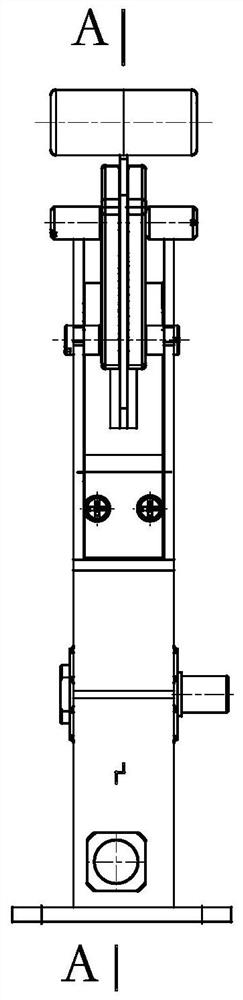
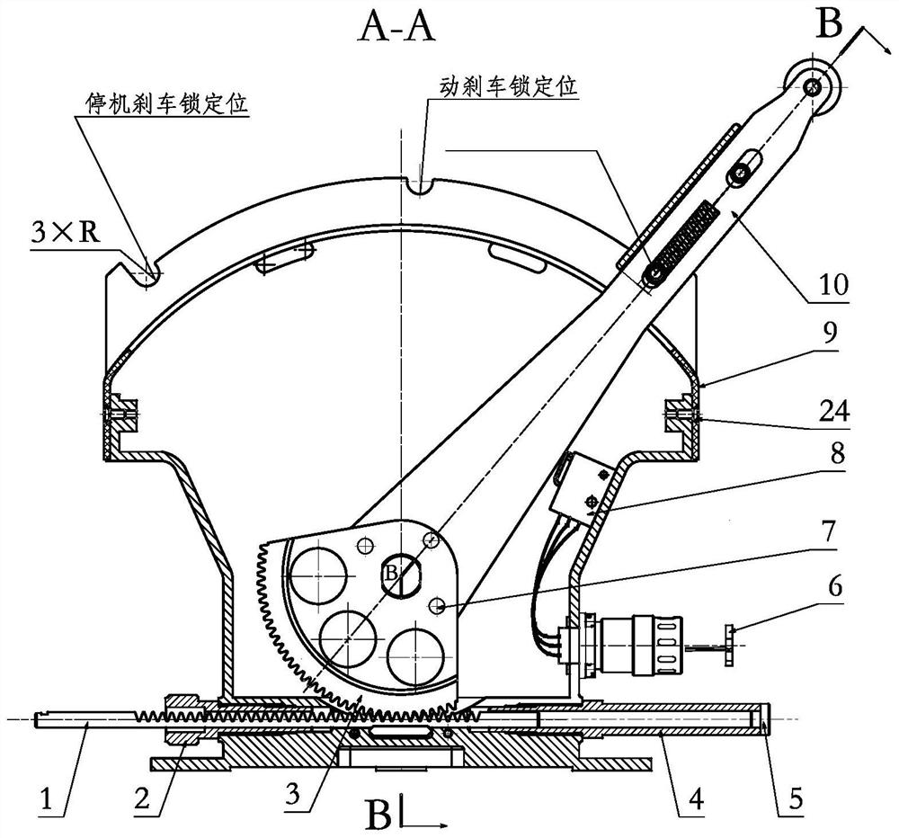
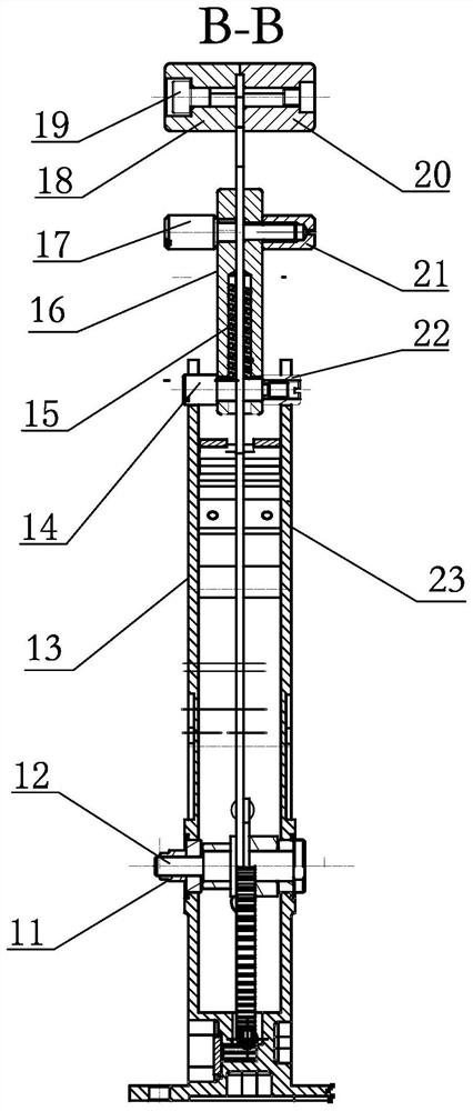
[0029] A manual brake operating device, such as figure 1 , figure 2 , image 3 As shown, the manual brake control device includes a rack 1, a solenoid 2, a gear 3, a sleeve 4, an end cover 5, an electrical connector 6, a rivet 7, a micro switch 8, a dust cover 9, a rocker arm 10, a lock Tight nut 11, rotating shaft 12, housing 13, lock pin 14, spring 15, pull bar 16, trigger 17, handle 18, screw 19, handle 20, nut 21, lock pin 22, cover plate 23, screw 24.

[0030] The rack 1 is connected with the moving parts of the force transmission mechanism, and transmits the operating force applied to the handle 18 and the handle 20 to the brake device; the solenoid 2 is fixed on the housing 13 through threaded connection, and the force transmission mechanism is installed and positioned. Rack 1 is positioned and guided; gear 3 and rocker arm 10 are rigidly connected by riveting rivets 7, and the ste...


PUM


Abstract

The invention discloses a hand brake control device. According to the hand brake control device, the control force is transmitted to a brake device through a gear and rack mechanism, and relatively small control force is applied to control stroke through gear and rack transmission so as to meet the requirements of a relatively large braking load and the stroke thereof. The hand brake control device has the functions of dynamic braking and stopping braking, can respectively lock stopping braking, emergency braking and braking release states, misoperation prevention measures, and the functions of monitoring and alarming a braking signal and a braking release signal.

Description

technical field [0001] The invention relates to the field of brake devices, in particular to a manual brake control device used in the brake system of an aircraft cockpit. Background technique [0002] When the aircraft is performing parking braking, emergency braking or rotor braking, the pilot pulls the brake handle to transmit the force and displacement to the braking device to achieve braking. [0003] In the Chinese patent CN207848258U, a brake control device belonging to the technical field of oil and gas is disclosed. It is a turbine brake control device and a pumping unit device. The switch blade is composed of a worm lifter to drive the adjustment rod to move downward, so that the locking teeth on the safety switch blade and the safety gear are locked to prevent the lateral deviation of the locking teeth and the safety gear and ensure the braking effect. The turbine brake control device and the pumping unit are powered by the turbine lift and are not suitable for m...

Claims


Application Information

Patent Timeline
Patent Type & Authority Applications(China)
IPC IPC(8): F16D65/18F16D66/00B64C25/44F16D121/14F16D127/06
CPCB64C25/44F16D65/18F16D66/00F16D2121/14F16D2127/06
Inventor 詹永鹏
Owner 贵州新安航空机械有限责任公司
Why Eureka
Try Eureka