Collecting pipe for heat exchanger and heat exchanger

A heat exchanger and header technology, applied in the field of heat exchange equipment, can solve problems such as operational safety accidents, external heating, etc., and achieve the effect of increasing the contact area, improving the efficiency of heat exchange, and improving the effect of heat exchange

Inactive Publication Date: 2020-12-11
GUANGZHOU JIEMA HEAT EXCHANGE EQUIP
View PDF6 Cites 0 Cited by
  • Summary
  • Abstract
  • Description
  • Claims
  • Application Information

AI Technical Summary

Problems solved by technology

[0003] During the use of the current heat exchanger, the use of the hot steam heat exchanger can enable rapid heat exchange inside, but when the current hot steam heat exchange equipment is in use, the internal heat exchange inner chassis and the outer main chassis Connected to each other, so that the heat of heat exchange will also flow to the inside of the main chassis, making the outside hot and prone to operational safety accidents

Method used


Image

  • Collecting pipe for heat exchanger and heat exchanger
  • Collecting pipe for heat exchanger and heat exchanger
  • Collecting pipe for heat exchanger and heat exchanger

Examples


Embodiment 1

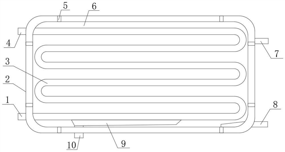
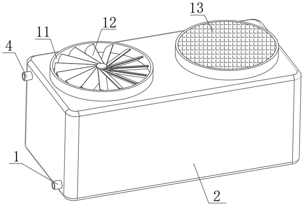
[0029] A header and heat exchanger for heat exchangers such as Figure 1-3 As shown, including the main chassis 2, both ends of the top inner wall and the bottom inner wall of the main chassis 2 are fixed with vertically arranged fixed connecting rods 5, and the fixed connecting rods 5 at the top position and the bottom position are fixed with the same The heat exchange inner chassis 6 arranged horizontally, the heat exchange coil 3 arranged horizontally is fixed between the inner walls of both ends of the heat exchange inner chassis 6, the bottom of one end of the main chassis 2 is provided with a first hole, and the first hole is sleeved with The heat exchange inlet 1 is arranged horizontally, one end of the heat exchange inlet 1 communicates with the bottom of the heat exchange coil 3, a second hole is opened on the top of one end of the main chassis 2, and the inner wall of the second hole is sleeved with The heat exchange liquid outlet pipe 4 is arranged horizontally, and...

Embodiment 2

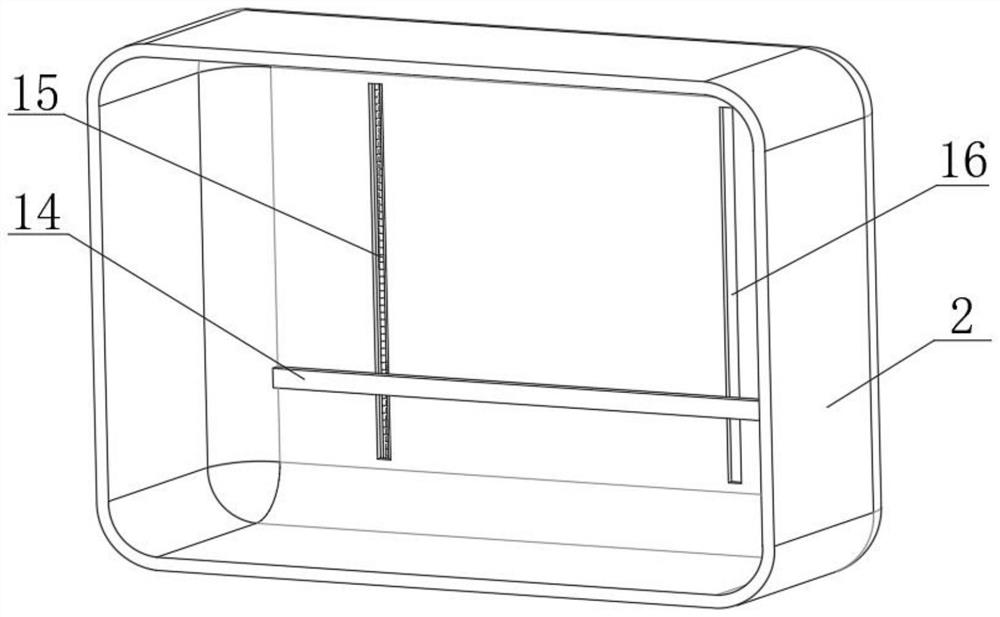
[0033] A header and heat exchanger for heat exchangers such as Figure 1-4 As shown, the outer peripheral wall of the heat exchange coil 3 is provided with spherical tubes 17 arranged in a horizontal array, and the spherical tubes 17 communicate with the interior of the heat exchange coil 3 .

[0034] When this embodiment is in use, in Embodiment 2, on the basis of Embodiment 1, spherical tubes 17 are arranged on the outer wall of the heat exchange coil 3 in an array. The contact area of ​​the external water improves the overall heat transfer effect and improves the heat transfer efficiency.


PUM


Abstract

The invention belongs to the technical field of heat exchange equipment, and particularly relates to a collecting pipe for a heat exchanger and the heat exchanger. Aiming at the problems of an heat exchanger in the background art, the following scheme is provided. The collecting pipe comprises a main machine box; vertically-arranged fixing connecting rods are fixed to the two ends of the top innerwall and the bottom inner wall of the main machine box; a same horizontally-arranged heat exchange inner machine box is fixed between the fixing connecting rods at the top position and the bottom position; a horizontally-arranged heat exchange coil pipe is fixed between the inner walls of the two ends of the heat exchange inner machine box; a first hole is formed in the bottom of one end of the main machine box; a horizontally-arranged heat exchange liquid inlet is connected with the first hole in a sleeving mode; and one end of the heat exchange liquid inlet is communicated with the bottom of the heat exchange coil pipe. According to the collecting pipe for the heat exchanger and the heat exchanger, in the heat exchange process, a heat dissipation fan arranged at the top position can rapidly dissipate heat of a heat energy buffer area between the inner wall of the top of the main machine box and the heat exchange inner machine box, so that the outer wall of the main machine box is prevented from being too hot.

Description

technical field [0001] The invention relates to the technical field of heat exchange equipment, in particular to a header used for a heat exchanger and a heat exchanger. Background technique [0002] A heat exchanger is an energy-saving device that transfers heat between materials between two or more fluids at different temperatures. It transfers heat from a fluid with a higher temperature to a fluid with a lower temperature, so that the fluid temperature reaches the process The specified index is to meet the needs of the process conditions, and it is also one of the main equipment to improve energy utilization. The heat exchanger industry involves nearly 30 industries such as HVAC, pressure vessels, reclaimed water treatment equipment, chemical industry, petroleum, etc., forming an industrial chain with each other. [0003] During the use of the current heat exchanger, the use of the hot steam heat exchanger can enable rapid heat exchange inside, but when the current hot s...

Claims


Application Information

Patent Timeline
Patent Type & Authority Applications(China)
IPC IPC(8): F28D7/08F28F1/08F28F9/00F28F19/01
CPCF28D7/082F28F1/08F28F9/00F28F19/01
Inventor 冯育周江广华陈飞勇
Owner GUANGZHOU JIEMA HEAT EXCHANGE EQUIP
Why Eureka
Try Eureka