
Angular velocity measurement method of fiber-optic gyroscope

A fiber optic gyroscope and angular velocity detection technology, applied in the field of gyroscopes, can solve the problems of deteriorating detection sensitivity, affecting the short-term walking performance of the gyroscope, and uneven noise spectrum, so as to reduce the noise floor, improve the short-term walking performance, reduce Effect of Phase Error

Active Publication Date: 2020-12-11
PEKING UNIV
View PDF5 Cites 4 Cited by
  • Summary
  • Abstract
  • Description
  • Claims
  • Application Information

AI Technical Summary

Problems solved by technology

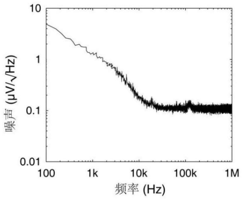
However, after analyzing the noise spectrum by collecting the interference signals of the two beams of light, it is found that the noise spectrum is not flat, and the low-frequency noise is obviously higher than the high-frequency part, such as Figure 4 shown
Therefore, for a large fiber optic ring (its length is 30km and its eigenfrequency is 3.3kHz), its modulation frequency will be much lower than that of a small fiber optic ring, and it will fall into Figure 4 The low-frequency part with high 1 / f noise shown will greatly affect the short-term wandering performance of the gyroscope and degrade the detection sensitivity. The influence of 1 / f noise cannot be ignored in ultra-large and high-precision fiber optic gyroscopes

Method used


Image

  • Angular velocity measurement method of fiber-optic gyroscope
  • Angular velocity measurement method of fiber-optic gyroscope
  • Angular velocity measurement method of fiber-optic gyroscope

Examples


Embodiment Construction

[0059] Exemplary embodiments of the present disclosure will be described in more detail below with reference to the accompanying drawings. Although exemplary embodiments of the present disclosure are shown in the drawings, it should be understood that the present disclosure may be embodied in various forms and should not be limited by the embodiments set forth herein. Rather, these embodiments are provided for more thorough understanding of the present disclosure and to fully convey the scope of the present disclosure to those skilled in the art.

[0060] It should be noted that, unless otherwise specified, technical terms or scientific terms used in this application shall have the usual meanings understood by those skilled in the art to which this application belongs.

[0061] In addition, the terms "first" and "second", etc. are used to distinguish different objects, not to describe a specific order. Furthermore, the terms "include" and "have", as well as any variations the...


PUM


Abstract

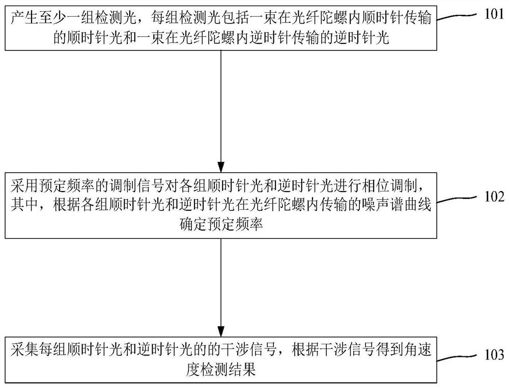
The invention provides an angular velocity detection method of a fiber-optic gyroscope, which comprises the following steps of generating at least one group of detection light, wherein each group of detection light comprises a beam of clockwise light which is transmitted clockwise in the fiber-optic gyroscope and a beam of anticlockwise light which is transmitted anticlockwise in the fiber-optic gyroscope, performing phase modulation on each group of clockwise light and counterclockwise light by adopting a modulation signal with a preset frequency, and determining the preset frequency according to the noise spectrum curve of each group of clockwise light and counterclockwise light transmitted in the fiber-optic gyroscope, and acquiring interference signals of each group of clockwise lightand anticlockwise light, and obtaining an angular velocity detection result according to the interference signals. The frequency of the modulation signal is set in the broadband noise frequency band,the noise floor can be greatly reduced, and the short-time migration performance of the fiber-optic gyroscope is improved. And meanwhile, the influence of the trailing effect is reduced due to the pull-open of the frequency points, so that the phase error caused by 1 / f noise can be reduced to a great extent, the short-time migration performance of the fiber-optic gyroscope is improved, and the index of the ultra-high-precision fiber-optic gyroscope strides into a new step.

Description

technical field [0001] The present application relates to the technical field of gyroscopes, in particular to a method for detecting angular velocity of a fiber optic gyroscope. Background technique [0002] A fiber optic gyroscope is a sensor that measures the angular velocity of an object's inertial motion. Due to its high precision, stable performance, good reliability, strong anti-interference ability and long life, it is widely used in missiles, aviation, aerospace, navigation and other fields. [0003] The basic working principle of the optical gyroscope is: when two beams of light with the same characteristics in a closed optical path are respectively transmitted in the clockwise (CW) direction and counterclockwise (CCW) direction, if the optical path rotates, the two beams will produce the same The phase difference related to the rotation angular velocity, so that the rotation angular velocity of the closed optical path can be obtained according to the interference ...

Claims


Application Information

Patent Timeline
IPC IPC(8): G01C19/72
CPCG01C19/721
Inventor 操玉文何动张丁凡周桐阳春霞曾卫益朱兰鑫陈彦钧李正斌蒋云
Owner PEKING UNIV
Learn More