Release control system and method suitable for residual current detection/protection field

A technology of residual current and control method, applied in the direction of measuring current/voltage, protection switch operation/release mechanism, instrument, etc., to achieve the effect of reasonable structure, convenient use and increased flexibility

Pending Publication Date: 2020-12-11
上海谷为电子科技有限公司
View PDF7 Cites 0 Cited by
  • Summary
  • Abstract
  • Description
  • Claims
  • Application Information

AI Technical Summary

Problems solved by technology

There is still room for improvement in the structure and performance of this patent

Method used


Image

  • Release control system and method suitable for residual current detection/protection field
  • Release control system and method suitable for residual current detection/protection field

Examples


Embodiment Construction

[0035] The present invention will be described in detail below in conjunction with specific embodiments. The following examples will help those skilled in the art to further understand the present invention, but do not limit the present invention in any form. It should be noted that those skilled in the art can make several changes and improvements without departing from the concept of the present invention. These all belong to the protection scope of the present invention.

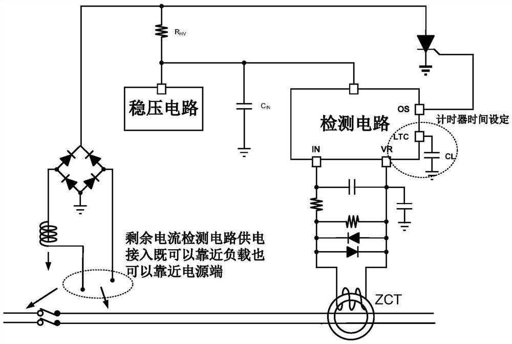
[0036] Such as Figure 1-2 As shown, a release control system applicable to the field of residual current detection / protection provided according to the present invention includes: a voltage stabilizing circuit component, a detection circuit component, a timer time setting component and a timer control component;

[0037] The voltage stabilizing circuit part is connected with the detection circuit part;

[0038] The detection circuit part is connected with the timer time setting part;

[0039] The vol...


PUM


Abstract

The invention provides a release control system and method suitable for the field of residual current detection/protection. The release control system comprises a voltage stabilizing circuit component, a detection circuit component, a timer time setting component and a timer control component. The voltage stabilizing circuit component is connected with the detection circuit component, the detection circuit part is connected with the timer time setting part, and the voltage stabilizing circuit component is connected with the timer control component. According to the invention, the stored residual current detection result is reset through the adjustable timer, so that the flexibility of the assembly end is improved, and the assembly end can be connected to a power supply end and can also beconnected to a load end, the design of the adjustable timer is characterized in that the time is not limited to be adjusted through an external capacitor, the time can also be adjusted through an external resistor, and programming is carried out through other programmable interfaces such as an I2C/SPI bus to control the timing time of the timer.

Description

technical field [0001] The present invention relates to the technical field of residual current detection, in particular to a release control system and method applicable to the field of residual current detection / protection. Background technique [0002] In traditional residual current detection applications, after the system detects that the residual current exceeds the preset threshold, it will latch this state, then turn on the drive circuit to drive the thyristor component, and pull down the output of the rectifier bridge to generate current, which will generate a magnetic field to pull the electromagnetic The iron controls the tripping of the main circuit switch, so as to achieve the purpose of residual current detection / protection. But a major problem with the traditional structure is that once the residual current is detected to exceed the set threshold, the system will lock this state, and this state will not be automatically released unless the system is powered on...

Claims


Application Information

Patent Timeline
Patent Type & Authority Applications(China)
IPC IPC(8): H01H71/12G01R19/165H03K17/22H03K17/90
CPCH01H71/12G01R19/16571H03K17/90H03K17/22
Inventor 包章尧周纲
Owner 上海谷为电子科技有限公司
Why Eureka
Try Eureka