
Vibrating chute concentrating machine for coal mining and using method thereof

A vibrating and concentrator technology, applied in the field of coal mining machinery, can solve problems such as environmental pollution, easy blockage, tailings that cannot be processed in time, and achieve the effect of increasing the spraying range and avoiding blockage

Inactive Publication Date: 2020-12-15
贾兵兵
View PDF7 Cites 2 Cited by
  • Summary
  • Abstract
  • Description
  • Claims
  • Application Information

AI Technical Summary

Problems solved by technology

[0003] The current chute concentrator still has the following deficiencies: 1. When feeding materials, it is often prone to blockage, and generally needs to be cleaned manually, making the production inconsistent; 2. The tailings produced by the chute concentrator cannot be timely 3. The selected ore is often not easily removed, so we propose a vibrating chute concentrator for coal mining and its use method to solve the above-mentioned problems

Method used


Image

  • Vibrating chute concentrating machine for coal mining and using method thereof
  • Vibrating chute concentrating machine for coal mining and using method thereof
  • Vibrating chute concentrating machine for coal mining and using method thereof

Examples


Embodiment 1

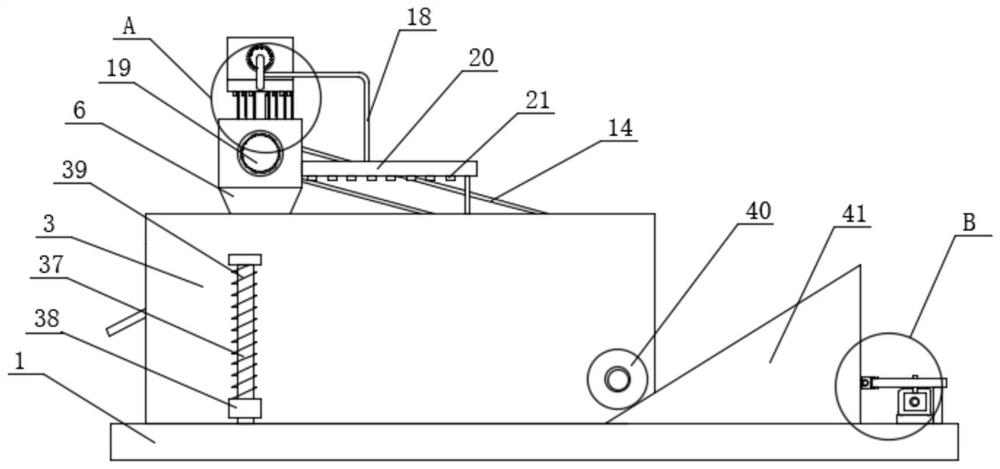
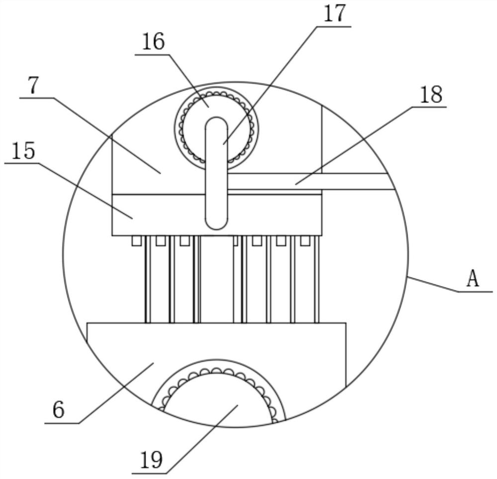
[0045] Embodiment one: if Figure 1-10 As shown, a vibrating chute concentrator used in coal mining includes a base 1, and the top of the base 1 is fixedly installed with a collection box 2 and is slidably connected with an installation pipe 3, and the collection box 2 is located in the installation pipe 3, and the installation pipe 3 is fixedly installed with a clip 4, which is sealed and bonded to the collection box 2, and a feeding pipe 6 is fixedly installed inside the installation pipe 3, and the top of the feeding pipe 6 extends to the top of the installation pipe 3 and is fixedly installed with a spray assembly , one side of the feeding pipe 6 is fixedly installed with a drive motor 19, the feeding pipe 6 is provided with a feeding assembly, the output shaft of the driving motor 19 extends into the feeding pipe 6 and is connected to the feeding assembly in transmission, and the transmission connection in the installation pipe 3 There is a material transfer component, an...

Embodiment 2

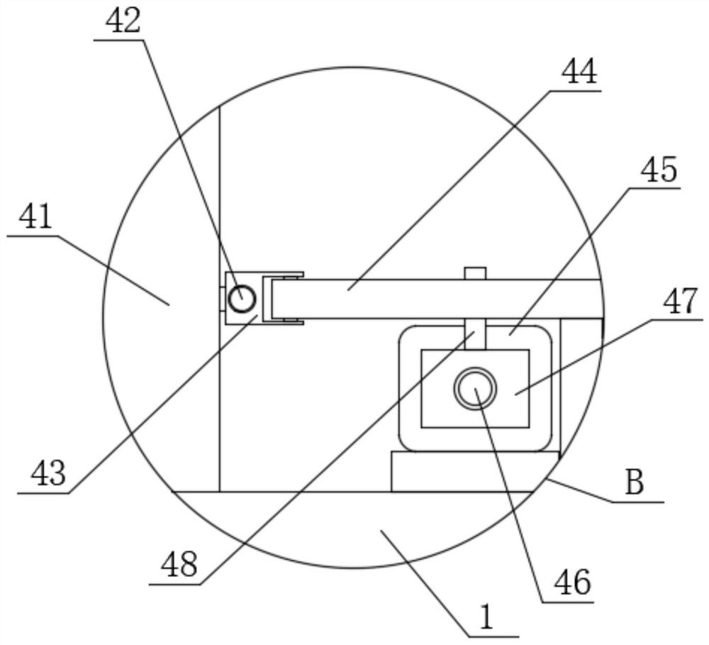
[0058] Embodiment two: if Figure 11-15 As shown, a vibrating chute concentrator used in coal mining, the difference between this embodiment and Embodiment 1 is that the driving assembly includes a transmission motor 45 fixedly installed on the top side of the base 1, and the output shaft of the transmission motor 45 is fixed Drive screw rod 46 is installed, and threaded plate 47 is threadedly connected on the drive screw rod 46, and the top of thread plate 47 is fixedly installed with stop shaft 48, and the top side of base 1 is connected with drive ring 44 in rotation, and the sliding connection in drive ring 44 is limited. Position plate 65, stop shaft 48 runs through limit plate 65 and is connected with limit plate 65 in rotation, one side of drive ring 44 is connected with slide plate 43 in rotation, one side of U-shaped inclined plate 41 is fixedly installed with connecting rod 42, connecting rod 42 runs through the slide plate 43 and is slidably connected with the slide...


PUM


Abstract

The invention discloses a vibrating chute concentrating machine for coal mining and a using method thereof. The vibrating chute concentrating machine comprises a base, a collecting box is fixedly mounted at the top of the base, a mounting pipe is slidably connected to the top of the base, the collecting box is located in the mounting pipe, a clamping strip is fixedly mounted in the mounting pipe,and the clamping strip is attached to the collecting box in a sealed mode. A feeding pipe is fixedly installed in the mounting pipe, the top of the feeding pipe extends to the position above the mounting pipe and is fixedly provided with a spraying assembly, and a driving motor is fixedly installed on one side of the feeding pipe. Stable feeding of coal briquettes can be achieved, so that it is guaranteed that blocking does not occur when the coal briquettes are subjected to concentrating, a conveying belt can be automatically cleaned in time when the coal briquettes are subjected to concentrating, tailings are effectively prevented from being attached to the conveying belt, and good environmental protection performance is achieved; and meanwhile, the sorted coal briquettes can be conveniently and automatically moved out, so that the technical scheme has good practicability and convenience in use.

Description

technical field [0001] The invention relates to the technical field of coal mine machinery, in particular to a vibrating chute concentrator used in coal mine mining and a method for using the same. Background technique [0002] Chute beneficiation is a method of beneficiation using water flowing along an inclined plane. In the chute, ore particles of different densities are stratified under the action of water flow dynamics, ore gravity, friction between ore particles and the bottom of the trough, etc. As a result, the ore particles with high density are concentrated in the lower layer and move forward along the bottom of the tank at a relatively low speed. While feeding ore, they are discharged out of the tank or stay at the bottom of the tank. After a period of time, they are discharged out of the tank intermittently. The small ore particles are distributed in the upper layer and are carried away by the water flow at a relatively high speed. [0003] The current chute con...

Claims


Application Information

Patent Timeline
Patent Type & Authority Applications(China)
IPC IPC(8): B03B5/62B03B11/00B08B3/02
CPCB03B5/62B03B11/00B08B3/02
Inventor 贾兵兵候磊
Owner 贾兵兵
Learn More