Hydrostatic pressure guide rail system with actively controllable oil film thickness

A hydrostatic guide rail, oil film thickness technology, applied in large fixed members, metal processing machinery parts, metal processing equipment and other directions, can solve problems such as changes in guide rail stiffness and load capacity, reduce structural size, reduce difficulty, and excellent oil film. The effect of thickness dynamic control capability

Active Publication Date: 2020-12-15
INST OF MACHINERY MFG TECH CHINA ACAD OF ENG PHYSICS
View PDF19 Cites 3 Cited by
  • Summary
  • Abstract
  • Description
  • Claims
  • Application Information

AI Technical Summary

Problems solved by technology

However, the above active control methods are mainly implemented by directly changing the pressure or flow in the oil chamber of the guide rail. While realizing the control of the oil film thickness, the pressure and flow of the oil chamber in the original design of the guide rail will change, resulting in the rigidity and load capacity of the guide rail. also changed

Method used


Image

  • Hydrostatic pressure guide rail system with actively controllable oil film thickness
  • Hydrostatic pressure guide rail system with actively controllable oil film thickness
  • Hydrostatic pressure guide rail system with actively controllable oil film thickness

Examples


Embodiment 1

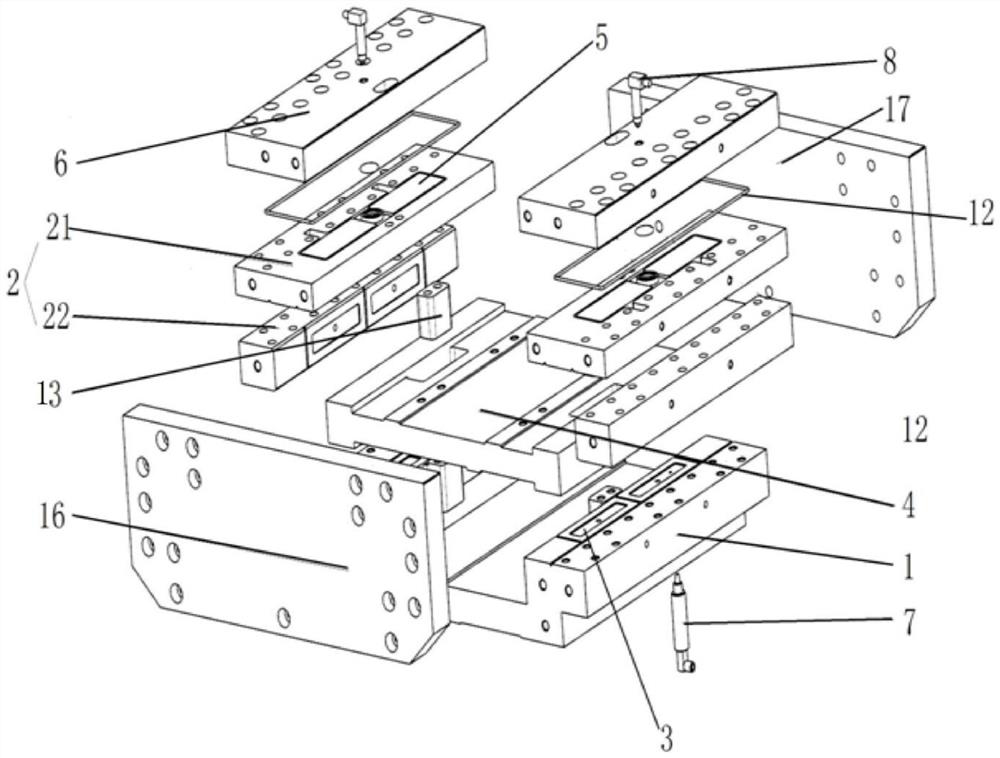
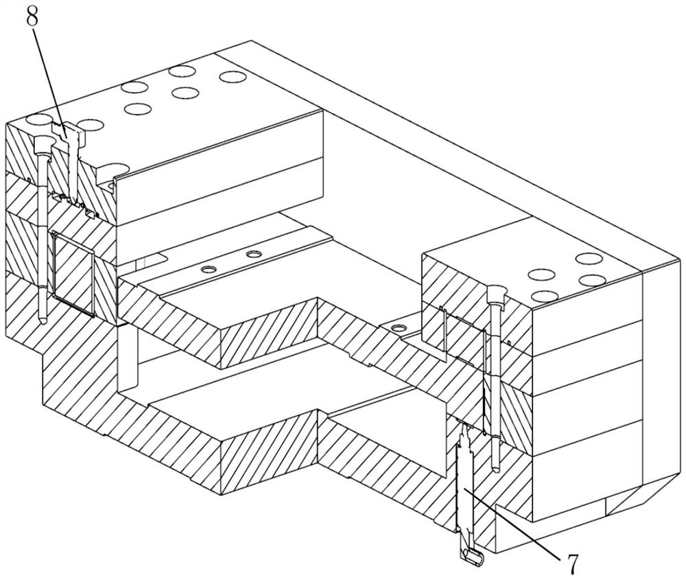
[0049] Such as figure 1 As shown in and , this embodiment provides a hydrostatic guide rail with actively controllable oil film thickness. The base 1 is provided with a sliding plate 4 , a thrust plate assembly 2 and a reinforcing block 13 . The base 1 and the thrust plate assembly 2 jointly form a left-right symmetrical first guide rail 90 and a second guide rail 91, which are distributed on both sides of the base 1, and each of the first guide rail 90 and the second guide rail 91 forms a semi-enclosed "C"-shaped structure. . A pressure cover plate 6 is provided directly above the upper thrust plate 21 .

[0050] The structure of slide plate 4 is as Figure 9 As shown, the gap between the first guide rail sliding surface of the slide plate 4 and the first guide rail 90 is 10 μm-40 μm.

[0051] The gap between the sliding surface of the second guide rail of the slide plate 4 and the second guide rail 91 is 10 μm-40 μm.

[0052] The base 1 and the thrust plate assembly are ...

Embodiment 2

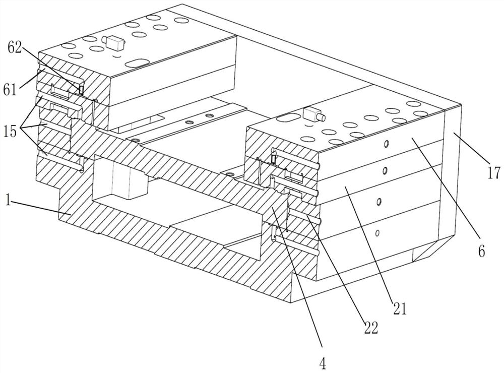
[0062] Such as Figure 10 As shown, further optimization on the basis of Embodiment 1, the base 1 is provided with a reinforcement block 13 in the middle of the cantilever between the first guide rail 90 and the second guide rail 91 and the upper thrust plate 21 in the middle of the moving direction of the slide plate 4 .

[0063] The base 1 is provided with a lower connecting plate 17 and an upper connecting plate 16 at the end of the moving direction of the slide plate 4 . The upper connecting plate 16 and the lower connecting plate 17 are respectively connected with the base 1, the thrust plate 21 and the pressure cover plate 6 using bolts. The sliding plate 4 is provided with through grooves on the left and right sides of the middle part of its moving direction, and the reinforcing blocks 13 pass through the grooves without contacting.

[0064] The base 1, the reinforcing block 13, the upper thrust plate 21 and the pressure cover plate 6 are connected by bolts. The joint...


PUM


Abstract

The invention discloses a hydrostatic pressure guide rail system with actively controllable oil film thickness. The hydrostatic pressure guide rail system comprises a base, a thrust plate assembly, aslide carriage, a pressure cover plate, a temperature sensing device and a displacement sensing device, wherein the base, the thrust plate assembly and the slide carriage form a main oil film cavity;the temperature sensing device collects temperature data of the main oil film cavity; the pressure cover plate and the thrust plate assembly form an auxiliary oil film cavity; the displacement sensingdevice collects displacement data of the thrust plate assembly in the auxiliary oil film cavity to obtain thickness data of a main oil film; and the pressure and the flow rate of the auxiliary oil film cavity are regulated on the basis of the real-time data of the temperature and the thickness of the main oil film without changing the pressure and the flow rate of the main oil film cavity, so that the bearing capability and the rigidity of a hydrostatic pressure guide rail can be ensured while the thickness of the main oil film is controlled. The main oil film is indirectly controlled throughcontrolling an auxiliary oil film, so that the control on the main oil film is realized, and the change of the rigidity and the load capability of the guide rail is also avoided.

Description

technical field [0001] The invention relates to the technical field of ultra-precision processing equipment for optical parts, in particular to a hydrostatic guide rail system with actively controllable oil film thickness. Background technique [0002] Hydrostatic guide rail is a kind of linear motion guide rail in which hydraulic oil with pressure is input into the oil chamber of the guide rail working surface through a throttle to form a pressure oil film, so that pure liquid friction is formed between the guide rail surfaces. Compared with traditional linear guides, it has the characteristics of wide working speed range, high motion precision, small friction coefficient, low driving power, long working life and good dynamic and static stiffness. Based on this, hydrostatic guide rails are widely used in the fields of precision machining, ultra-precision machining and measurement. [0003] The static pressure guide rail is generally composed of a base, a thrust plate and a...

Claims


Application Information

Patent Timeline
Patent Type & Authority Applications(China)
IPC IPC(8): B23Q1/38B23Q1/01
CPCB23Q1/017B23Q1/385
Inventor 李星占岳友飞苏星魏巍李加胜阳红
Owner INST OF MACHINERY MFG TECH CHINA ACAD OF ENG PHYSICS
Why Eureka
Try Eureka