Supercharge Your Innovation With Domain-Expert AI Agents!

Unmanned aerial vehicle-mounted laser performance device

An airborne laser and unmanned aerial vehicle technology, applied in the direction of circuit devices, battery circuit devices, unmanned aircraft, etc., can solve the problems of unusable, discounted laser effect, and restricting the development of laser, so as to increase the use time and solve the problem of The effect of the limitations of the installation conditions

Pending Publication Date: 2020-12-15
深圳镭士兰科技有限公司
View PDF0 Cites 1 Cited by
  • Summary
  • Abstract
  • Description
  • Claims
  • Application Information

AI Technical Summary

Problems solved by technology

[0002] With the development of science and technology, drones have been widely used as advanced technologies and products in industrial and commercial fields such as aerial photography, remote sensing mapping, agricultural spraying, film and television advertisements, and lasers are also a kind of high-tech equipment. It has the characteristics of directional light emission, extremely high brightness, extremely pure color, and great energy. Laser technology is used in many cutting-edge fields. In the field of civil entertainment, lasers are widely used as special lamps on stages, landscapes, landmarks, advertisements, search Marking and other industries. At present, laser lights on the market can only be installed in fixed locations due to site and space constraints. Many occasions with unsatisfactory installation conditions will greatly reduce the laser effect or cannot be used directly, which seriously restricts the laser industry. development of

Method used


Image

  • Unmanned aerial vehicle-mounted laser performance device
  • Unmanned aerial vehicle-mounted laser performance device
  • Unmanned aerial vehicle-mounted laser performance device

Examples


Embodiment Construction

[0023] The technical solutions in the embodiments of the present invention will be clearly and completely described below in conjunction with the accompanying drawings in the embodiments of the present invention. Obviously, the described embodiments are only some of the embodiments of the present invention, not all of them. Based on The embodiments of the present invention and all other embodiments obtained by persons of ordinary skill in the art without making creative efforts belong to the protection scope of the present invention.

[0024] see Figure 1-5 , the present invention provides a technical solution:

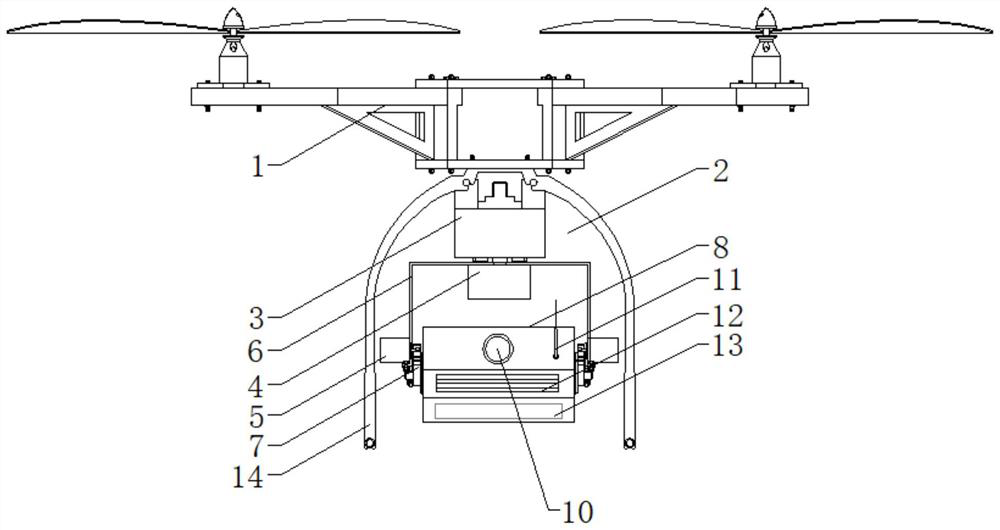
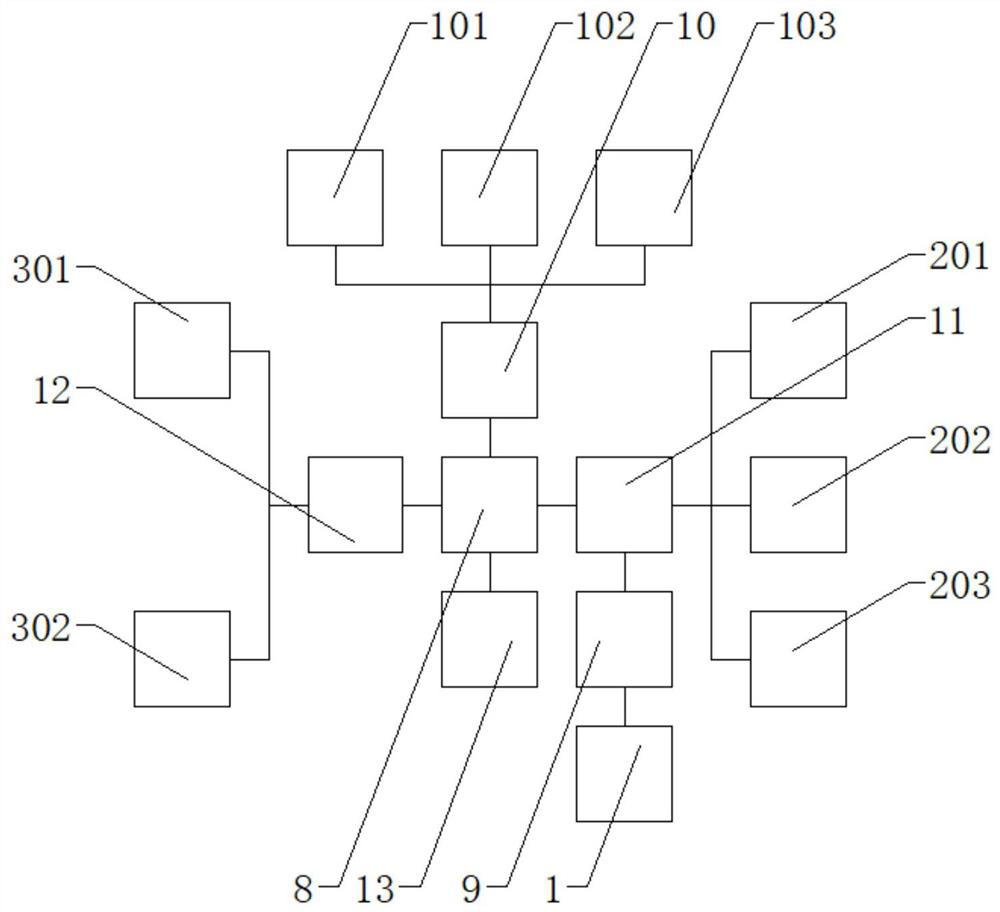
[0025] An unmanned aerial vehicle-mounted laser performance device, comprising an unmanned aerial vehicle carrier 1, a pan-tilt 2 is arranged at the center of the bottom of the unmanned aerial vehicle carrier 1, and the pan-tilt 2 includes a connecting seat 3, a horizontal steering motor 4, two vertical steering motors 5, U-shaped frame 6 and connecting frame 7, con...


PUM


Abstract

The invention relates to the technical field of unmanned aerial vehicles and laser lamps, in particular to an unmanned aerial vehicle-mounted laser performance device. The device comprises an unmannedaerial vehicle carrier, and a holder is arranged at the center of the bottom of the unmanned aerial vehicle carrier and comprises a connecting base, a horizontal steering motor, two vertical steeringmotors, a U-shaped frame and a connecting frame. The connecting base in the holder is connected to the center of the bottom of the unmanned aerial vehicle carrier through a bolt, and the horizontal steering motor is connected to the center of the U-shaped frame. A laser system is designed, turning on and turning off of a laser lamp can be achieved through a wireless signal receiving device, the functions of material pattern switching, graphic size zooming and the like are perfectly combined with an unmanned aerial vehicle, so that the limitation of mounting conditions is solved, and the laserperformance equipment can appear in any required place and even can project laser in an omnibearing and multi-angle manner during movement; The space flexibility of the laser performance equipment isimproved, and the application range of laser is greatly widened.

Description

technical field [0001] The invention relates to the technical field of drones and laser lights, in particular to a drone-borne laser performance device. Background technique [0002] With the development of science and technology, drones have been widely used as advanced technologies and products in industrial and commercial fields such as aerial photography, remote sensing mapping, agricultural spraying, film and television advertisements, and lasers are also a kind of high-tech equipment. It has the characteristics of directional light emission, extremely high brightness, extremely pure color, and great energy. Laser technology is used in many cutting-edge fields. In the field of civil entertainment, lasers are widely used as special lamps on stages, landscapes, landmarks, advertisements, search Marking and other industries. At present, laser lights on the market can only be installed in fixed locations due to site and space constraints. Many occasions with unsatisfactory ...

Claims


Application Information

Patent Timeline
IPC IPC(8): B64D47/02B64D47/08B64C27/08H02J7/00
CPCB64D47/02B64D47/08B64C27/08H02J7/00B64U10/10B64U2101/00
Inventor 徐志亮李坚张钊
Owner 深圳镭士兰科技有限公司
Features
  • R&D
  • Intellectual Property
  • Life Sciences
  • Materials
  • Tech Scout
  • Unparalleled Data Quality
  • Higher Quality Content
  • 60% Fewer Hallucinations
Learn More