Constant-pressure stabilizing device of diesel engine preheating system

A stabilizing device and diesel engine technology, applied in the direction of fuel heat treatment device, charging system, engine starting, etc., can solve the problem of large fluctuations in diesel pressure and flow, affecting the normal operation of flame glow plugs, flame injection preheaters, etc. Damage and other problems, to achieve the effect of occupying less space for the diesel engine, facilitating normal operation, solving the problem of stabilizing diesel pressure and balancing diesel flow

Pending Publication Date: 2020-12-15
HEBEI HUABEI DIESEL ENGINE
View PDF0 Cites 0 Cited by
  • Summary
  • Abstract
  • Description
  • Claims
  • Application Information

AI Technical Summary

Problems solved by technology

During cold start, the starter motor drives the diesel engine to indirectly provide power for the low-pressure pump. At this time, the speed of the low-pressure pump fluctuates greatly, resulting in large fluctuations in the pressure and flow of diesel oil in the low-pressure pump, which affects the normal operation of the flame glow plug;
[0005] Second, on the high-pressure common rail diesel engine, due to the difference in the fuel supply system, the pressure in the low-pressure diesel pipeline is relatively high. If it is directly connected to the oil inlet pipeline of the flame-injection preheater, the preheater cannot withstand it, and it is easy to cause flame injection. damage to the preheater

Method used


Image

  • Constant-pressure stabilizing device of diesel engine preheating system
  • Constant-pressure stabilizing device of diesel engine preheating system
  • Constant-pressure stabilizing device of diesel engine preheating system

Examples


Embodiment Construction

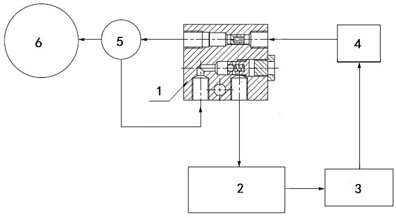
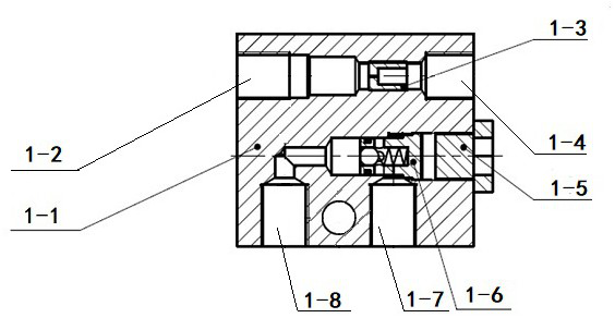
[0026] The present invention aims at the shortcomings in the prior art, and develops a constant pressure stabilization device for the diesel engine preheating system. An oil inlet pipeline and an oil return pipeline are arranged inside the communication valve. The two pipelines operate independently without interfering with each other, and can realize In the high-pressure common rail diesel engine preheating system, the function of reducing the oil inlet pressure and flow, stabilizing the oil pressure of the oil supply pipeline, and ensuring the normal flow direction of diesel oil is used to solve the problem of stabilizing diesel pressure and balancing diesel oil in the high-pressure common rail diesel engine flame preheating diesel pipeline flow problem.

[0027] Below in conjunction with accompanying drawing, the present invention is described in further detail:

[0028] Such as figure 1 As shown, a constant pressure stabilizing device for a diesel engine preheating system...


PUM


Abstract

The invention discloses a constant-pressure stabilizing device of a diesel engine preheating system, and belongs to the technical field of diesel engine preheating. A communicating valve, an oil tankcontaining diesel, a low-pressure pump, a fine diesel filter, an electromagnetic valve and a flame jet type preheater included and are integrated into an integrated structure, the low-pressure pump isused for pumping and pressurizing diesel from the oil tank, the fine diesel filter is used for filtering the diesel, the electromagnetic valve is used for controlling oil inflow and oil return of theflame jet type preheater, and the flame jet type preheater is used for combusting the diesel inside. The diesel flows into the communicating valve through the fine diesel filter, the communicating valve reduces pressure and flow of the diesel, and the fuel then flows into the flame jet type preheater through the electromagnetic valve to be combusted. Redundant diesel flowing into the flame jet type preheater flows back into the communicating valve through the electromagnetic valve and an oil return pipe and then returns to the oil tank. According to the designed communicating valve, a dampinghole is designed in an oil inlet way to reduce large pressure and limit flow of diesel, a one-way valve is additionally arranged on an oil return way and used for stabilizing oil pressure and guaranteeing the normal flowing direction of the diesel, and therefore the purpose of keeping the pressure of an oil supply system constant is achieved.

Description

technical field [0001] The invention relates to the technical field of diesel engine preheating, in particular to a constant pressure stabilizing device for a diesel engine preheating system, which is applied to a diesel supply pipeline of a flame injection preheater system. Background technique [0002] The flame preheating system is an important system for the cold start of the diesel engine. The diesel engine is a compression ignition engine without a spark plug to ignite. When the diesel engine is started in a cold state, due to the low initial speed of the crankshaft of the diesel engine, the diesel oil is easy to condense, so it is difficult for the gas entering the cylinder to rise to the self-ignition temperature during a cold start, and a preheating device is required to increase the intake air temperature. At present, the main preheating devices for diesel engines are electric heating wire preheaters and flame injection preheaters. [0003] There is no constant pr...

Claims


Application Information

Patent Timeline
IPC IPC(8): F02N19/04F02M31/16
CPCF02M31/16F02N19/04
Inventor 孙晓伟赵伟程袁晓桐董长龙赵子赛王兆阳许志强师帅楠
Owner HEBEI HUABEI DIESEL ENGINE
Why Eureka
Try Eureka