Mobile base station integrated box
A mobile base station, integrated box technology, applied in vibration suppression adjustment, wireless communication, energy reduction and other directions, can solve the problems of internal base station shaking, base station magnetic interference, large kinetic energy of the integrated box, etc., to avoid accumulation and increase contact The effect of resistance
- Summary
- Abstract
- Description
- Claims
- Application Information
AI Technical Summary
Problems solved by technology
Method used
Image

Examples
no. 1 example
[0029] Such as Figure 1-Figure 4 As shown, the present invention provides a technical solution of a mobile base station integrated box:
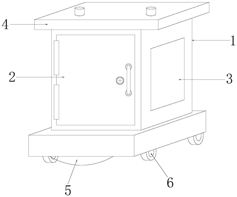
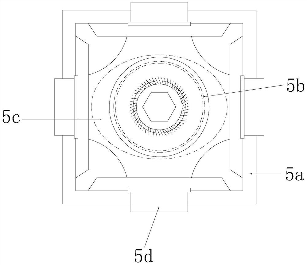
[0030] Such as Figure 1-Figure 2 As shown, a mobile base station integrated box, its structure includes a box body 1, a sealed door 2, a heat dissipation hole 3, a rain cover 4, a shifting protection device 5, and a moving wheel 6, and the sealed door 2 is arranged in front of the box body 1 The surface is connected by hinges, the heat dissipation hole 3 is arranged on the right side surface of the box body 1 and is an integrated structure, the rain cover 4 is arranged on the upper surface of the box body 1 and connected by electric welding, the moving protection device 5 is arranged on the lower surface of the box body 1 and connected by electric welding. The moving wheels 6 are installed on the four corners of the lower surface of the shifting device 5 and connected by buckling. The shifting device 5 includes a bottom frame 5a, a throug...
no. 2 example
[0039] Such as Figure 1-Figure 4 As shown, the present invention provides a technical solution of a mobile base station integrated box:
[0040] Such as Figure 1-Figure 2 As shown, a mobile base station integrated box, its structure includes a box body 1, a sealed door 2, a heat dissipation hole 3, a rain cover 4, a shifting protection device 5, and a moving wheel 6, and the sealed door 2 is arranged in front of the box body 1 The surface is connected by hinges, the heat dissipation hole 3 is arranged on the right side surface of the box body 1 and is an integrated structure, the rain cover 4 is arranged on the upper surface of the box body 1 and connected by electric welding, the moving protection device 5 is arranged on the lower surface of the box body 1 and connected by electric welding. The moving wheels 6 are installed on the four corners of the lower surface of the shifting device 5 and connected by buckling. The shifting device 5 includes a bottom frame 5a, a throug...
PUM
 Abstract
Description
Claims
Application Information
PatSnap Eureka turns technology decisions into work you can execute. Powered by our Innovation Knowledge Graph, it runs expert workflows across engineering, life sciences, materials and intellectual property. Get your review-ready output in minutes.


