Electronic circuit

a technology of electronic circuits and circuits, applied in the direction of identification means, semiconductor/solid-state device details, instruments, etc., can solve the problems of contact deterioration, contact deterioration serious, and deterioration of the characteristics of tfts

Inactive Publication Date: 2006-05-16
SEMICON ENERGY LAB CO LTD
View PDF102 Cites 29 Cited by
  • Summary
  • Abstract
  • Description
  • Claims
  • Application Information

AI Technical Summary

Benefits of technology

[0006]It is an object of the present invention to provide a reliable electronic circuit having a semiconductor layer, conductive interconnects, and good contacts between the semiconductor layer and the interconnects, the contacts being capable of withstanding thermal processing performed at or above 300° C.
[0015]Generally, a stoichiometric material (titanium nitride) containing nitrogen and titanium has excellent barrier characteristics and prevents diffusion of aluminum and silicon. However, the material shows a high contact resistance with silicon. Therefore, it is not desired to use such a material directly for formation of contacts. On the other hand, a stoichiometric material (titanium silicide) containing titanium and silicon exhibits a low contact resistance with the semiconductor layer consisting mainly of silicon. This is advantageous to form Ohmic contacts. However, aluminum tends to easily diffuse. For example, the aluminum of the second layer diffuses through the first layer, thus forming aluminum silicide in the semiconductor layer.
[0017]When a film of titanium silicide is formed, it is not necessary to intentionally add silicon. Titanium reacts with the silicon contained in the semiconductor layer. As a result, titanium silicide is automatically formed. For example, therefore, similar effects can be produced by depositing titanium containing less nitrogen onto the portion close to the semiconductor layer and depositing titanium containing more nitrogen onto the portion close to the second layer.

Problems solved by technology

Where electrodes should be formed on such a thin semiconductor layer, or an active layer, it has not been possible to make good contacts by the prior art techniques, because the thickness of the silicide layer grows almost up to the thickness of the semiconductor layer, thus severely deteriorating the electrical characteristics of the contacts.
When a stress such as a voltage is kept applied to the contacts for a long time, the contacts deteriorate seriously.
Where the thickness of the semiconductor layer of the TFTs is less than 1500 Å, the thermal processing greatly promotes growth of the silicide, leading to deterioration of the characteristics of the TFTs.

Method used


Image

  • Electronic circuit
  • Electronic circuit
  • Electronic circuit

Examples


example 1

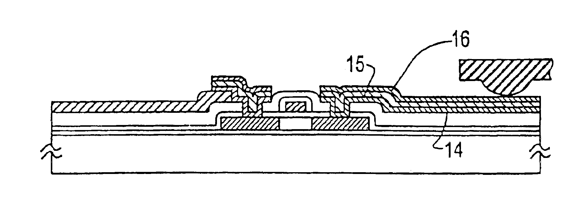
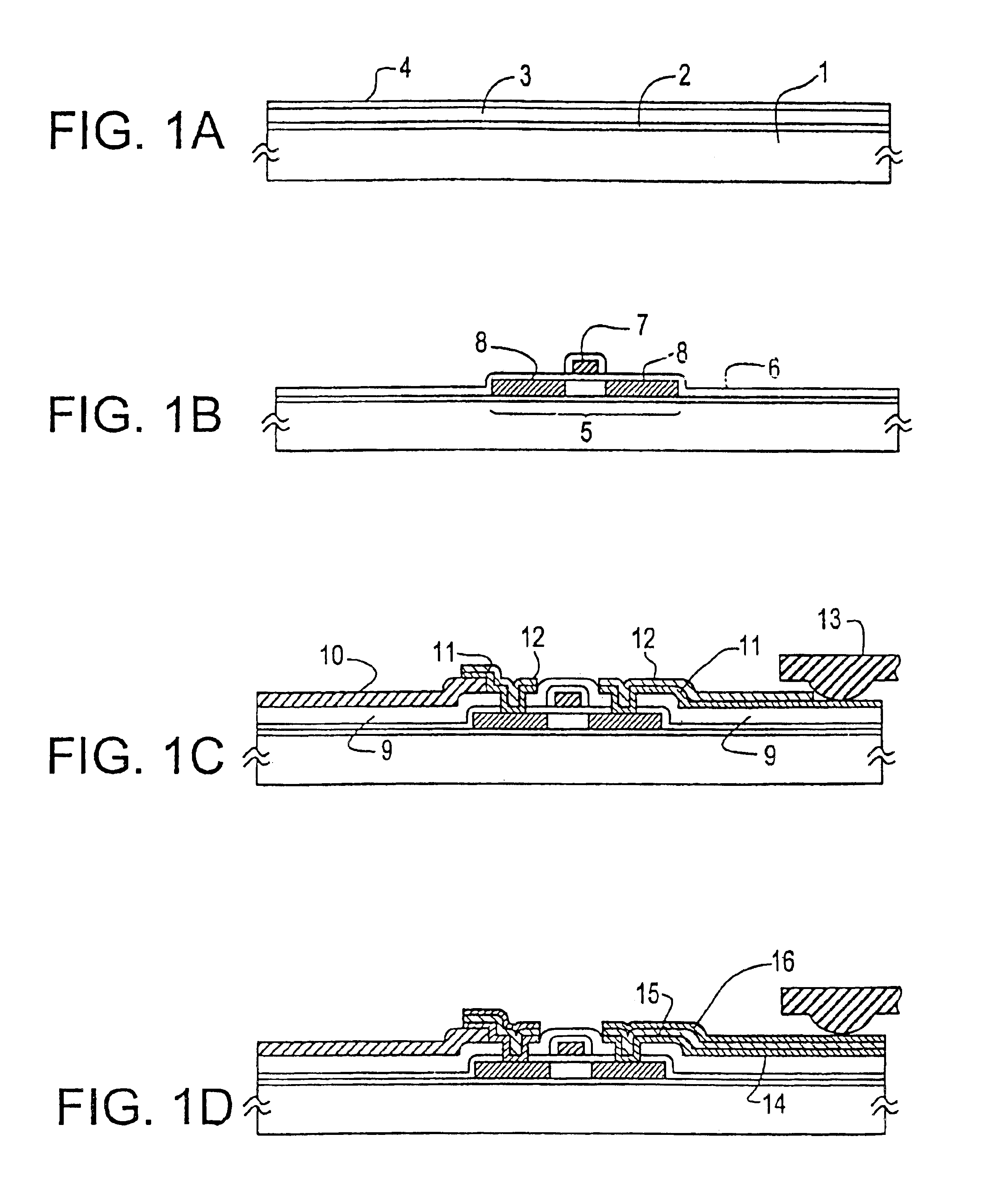
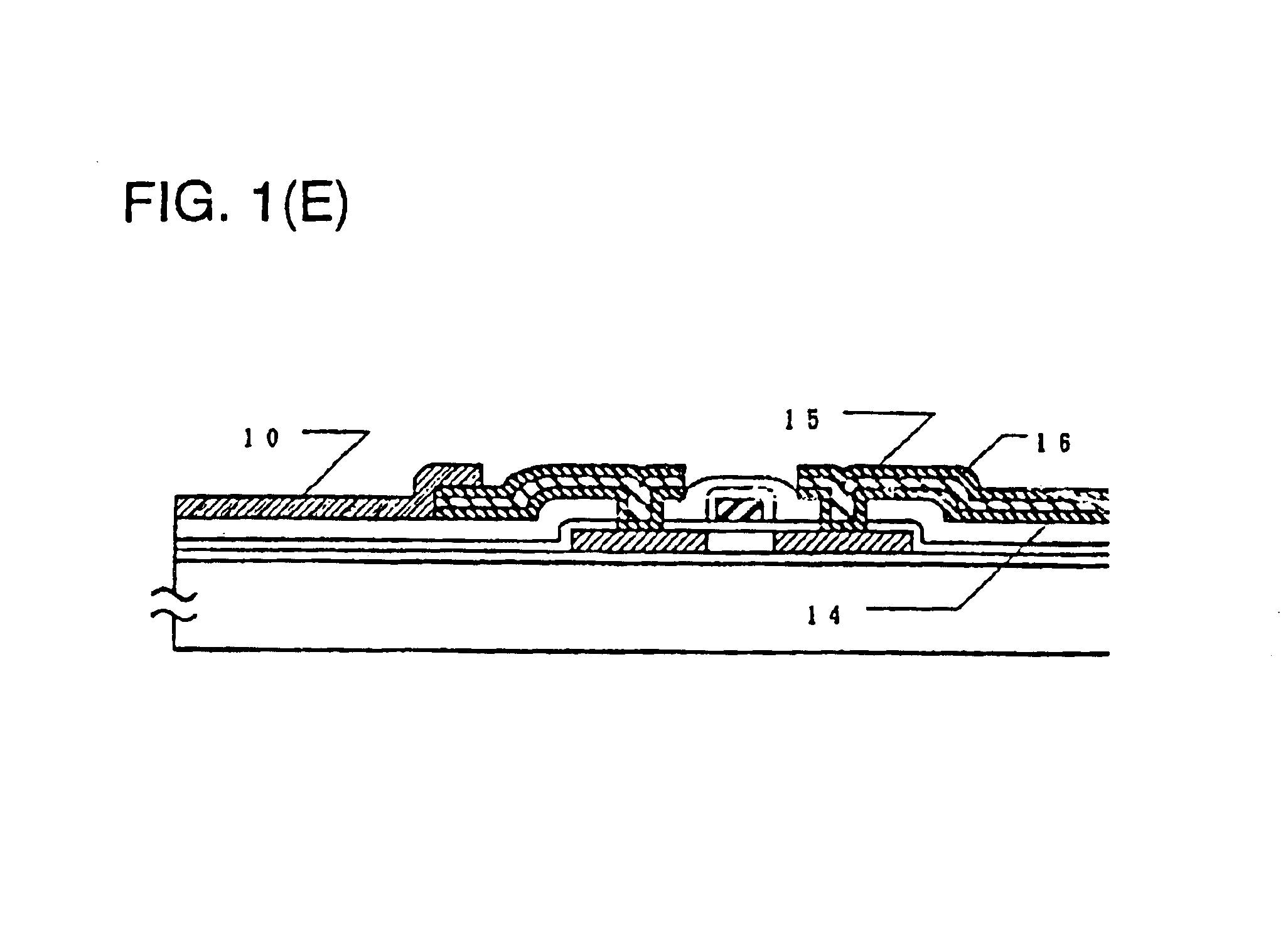
[0030]Example 1 is shown in FIGS. 1, (A)-(D), and 2, (A)-(B). FIGS. 1, (A)-(D), illustrate the sequence in which an electronic circuit having TFTs is fabricated. Description of conventional steps is omitted. First, silicon oxide was deposited as a silicon oxide film 2 forming a base film on a glass substrate 1 made of Corning 7059. An amorphous silicon film 3 having a thickness of 500 to 1500 Å, preferably 500 to 750 Å, was formed on the silicon oxide film 2. A protective layer 4 was formed on the amorphous silicon film 3. The laminate was annealed at 450 to 600° C. for 12 to 48 hours to crystallize the amorphous silicon film. Of course, laser annealing or other similar means can be used for the crystallization (FIG. 1(A)).

[0031]The silicon film was photolithographically patterned into island-shaped semiconductor regions 5. A silicon oxide film 6 having a thickness of 500 to 1500 Å, preferably 800 to 1000 Å, was formed on the semiconductor regions 5 to form a gate oxide film. Then, ...

example 2

[0043]The present example is described by referring to FIG. 1, (A)-(D), which conceptually illustrate the sequence in which an electronic circuit having TFTs is fabricated. Conventional steps are not described herein. First, silicon oxide was deposited as a silicon oxide base film 2 on a glass substrate 1. An amorphous silicon film 3 having a thickness of 100 to 1500 Å, preferably 100 to 750 Å, was formed on the silicon oxide film 2. A protective layer 4 was formed on the amorphous silicon film 3. The laminate was annealed at 450 to 600° C. for 12 to 48 hours to crystallize the amorphous silicon film. Of course, laser annealing or other similar means can also be used for the crystallization (FIG. 1(A)).

[0044]The silicon film was photolithographically patterned into island-shaped semiconductor regions 5. A silicon oxide film 6 having a thickness of 500 to 1500 Å, preferably 800 to 1000 Å, was formed on the semiconductor regions 5 to form a gate oxide film. Then, gate interconnects an...

example 3

[0049]The present example is shown in FIGS. 7, (A)-(H). First, silicon oxide was deposited as a silicon oxide film 202 on a glass substrate 201 made of Corning 7059. The silicon oxide film formed a base film and had a thickness of 1000 to 3000 Å. The substrate measured 300 mm×400 mm or 100 mm×100 mm. To form this oxide film, sputtering was effected within oxygen ambient. To make mass production more efficient, TEOS may be decomposed and deposited by plasma CVD.

[0050]Then, amorphous silicon was deposited as a film having a thickness of 300 to 5000 Å, preferably 500 to 1000 Å, by plasma CVD or LPCVD. This film was allowed to stand within an oxidizing ambient at 550 to 600° C. for 24 hours to crystallize the film. This step may also be carried out by laser irradiation. The crystallized silicon film was photolithographically patterned into island-shaped regions 203. A silicon oxide film 104 having a thickness of 700 to 1500 Å was formed by sputtering techniques.

[0051]An aluminum film ha...


PUM

PropertyMeasurementUnit
sheet resistanceaaaaaaaaaa
resistivitiesaaaaaaaaaa

Abstract

An electronic circuit formed on an insulating substrate and having thin-film transistors (TFTs) comprising semiconductor layers. The thickness of the semiconductor layers is less than 1500 Å, e.g., between 100 and 750 Å. A first layer consisting mainly of titanium and nitrogen is formed on the semiconductor layer. A second layer consisting aluminum is formed on top of the first layer. The first and second layers are patterned into conductive interconnects. The bottom surface of the second layer is substantially totally in intimate contact with the first layer. The interconnects have good contacts with the semiconductor layer.

Description

[0001]Divisional of prior application Ser. No. 10 / 193,162 filed Jul. 12, 2002, now U.S. Pat. No. 6,608,353 which is Divisional of Ser. No. 09 / 703,594 filed Nov. 2, 2000, now U.S. Pat. No. 6,448,612; which is a Divisional of Ser. No. 09 / 382,674 filed Aug. 25, 1999 now U.S. Pat. No. 6,166,414; which is Divisional of 09 / 041,702 filed Mar. 13, 1998 now U.S. Pat. No. 6,031,290; which is a Continuation of U.S. Ser. No. 08 / 636,917 filed Apr. 24, 1996 now U.S. Pat. No. 5,804,878; which is a Continuation of U.S. Ser. No. 08 / 162,357 filed Dec. 7, 1993 now Abandoned.FIELD OF THE INVENTION[0002]The present invention relates to an electronic circuit which is formed on an insulating substrate and has a thin semiconductor layer of silicon, for example, forming thin-film transistors, the thin semiconductor layer being required to be connected with conductive interconnects.BACKGROUND OF THE INVENTION[0003]Conventional thin-film devices such as insulated-gate FETs use a thin semiconductor film of sil...

Claims


Application Information

Patent Timeline
Patent Type & Authority Patents(United States)
IPC IPC(8): H01L21/00H01L21/8242H01L29/80H01L33/00H01L21/28C23C14/34G02F1/133G02F1/136G02F1/1368G09F9/35H01L21/02H01L21/3205H01L21/60H01L21/70H01L21/768H01L21/77H01L21/84H01L23/52H01L23/522H01L23/532H01L27/092H01L27/12H01L29/45H01L29/786H05B33/10H05B33/12H05B33/26H05B44/00
CPCH01L27/124H01L27/12H01L29/458H01L23/53223G02F1/1368H01L2924/10253H01L2924/13091H01L2924/00014H01L2224/45124H01L2924/00H01L2224/48
Inventor MIYAZAKI, MINORUMURAKAMI, AKANECUI, BAOCHUNYAMAMOTO, MUTSUO
Owner SEMICON ENERGY LAB CO LTD
Why Eureka
Try Eureka