Saw device with composite substrate for ultra high frequencies

A carrier substrate, positive frequency technology, applied in the direction of electrical components, impedance networks, etc.

Pending Publication Date: 2020-12-15
RF360新加坡私人有限公司
View PDF1 Cites 1 Cited by
  • Summary
  • Abstract
  • Description
  • Claims
  • Application Information

AI Technical Summary

Problems solved by technology

However, future applications will require devices up to...

Method used


Image

  • Saw device with composite substrate for ultra high frequencies
  • Saw device with composite substrate for ultra high frequencies
  • Saw device with composite substrate for ultra high frequencies

Examples


Embodiment Construction

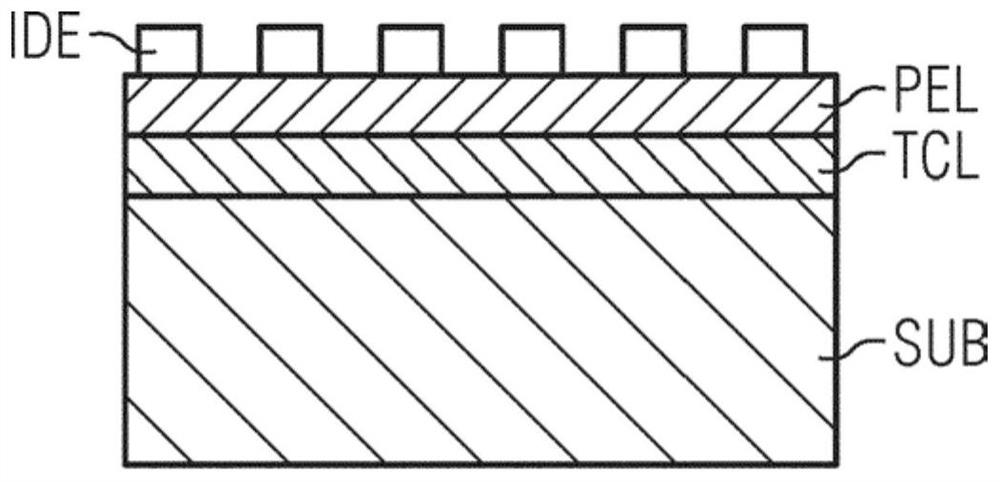
[0031] figure 1 The stack design of a SAW device according to the invention is shown in a schematic cross-sectional view. The carrier substrate SUB comprises a material with a high sound velocity. This thickness is sufficient to be mechanically stable for further handling and manipulation of the SAW device. A thin TCF compensation layer TCL is applied on the substrate and has a positive TCF adapted to compensate the negative TCF of other materials in the stack.

[0032] The next layer is the thin-film piezoelectric layer PEL, which needs to provide proper wave excitation and exhibit a suitably high electromechanical coupling. On the top interdigitated electrode IDE it is arranged to include a metallization adapted to provide the SAW device function of exciting the SAW and recovering electrical signals therefrom. Preferably, the interdigitated electrodes IDE form a resonator. Multiple resonators can form a filter in a ladder or lattice arrangement. However, the interdigita...


PUM

PropertyMeasurementUnit
Thicknessaaaaaaaaaa
Thicknessaaaaaaaaaa

Abstract

A SAW device having a stacked design of functional layers is proposed that is build up on a carrier substrate (SUB) that is chosen to provide a high acoustic velocity. The stack further comprises a thin TCF compensation layer (TCL), a thin film piezoelectric layer (PEL) and a set of interdigital electrodes (IDE) on top of the piezoelectric layer. Energy of the desired mode mainly in the high acoustic velocity material. Despite the high possible operating frequencies the SAW device can reliably be manufactured with present lithographic techniques.

Description

Background technique [0001] Today, SAW devices used in frequency filters of wireless communication devices need to comply with many specifications. Newly introduced standards or new developments constantly require that specifications be adapted and devices improved. Operation of wireless devices in multiple frequency bands that can be coupled in carrier aggregation mode requires high frequency stability under different temperature conditions and good rejection of out-of-band spurious modes. Especially when operating SAW devices at high power levels, individual solutions are required, each usually needing to be combined in one device. [0002] SAW devices using leaky surface waves exhibit losses due to undesired radiation of acoustic energy into the bulk substrate. Furthermore, extra bulk modes can reach the electrodes of the transducer and the resulting spurious signals can interfere with operation in the used frequency band. Further losses are due to the excitation of high...

Claims


Application Information

Patent Timeline
IPC IPC(8): H03H9/02
CPCH03H9/02559H03H9/02566H03H9/02574H03H9/02582H03H9/02834H03H9/02866H03H9/6406
Inventor M·纳普C·许克
Owner RF360新加坡私人有限公司
Why Eureka
Try Eureka