Surfboard spray pump structure with rapid heat dissipation effect

A technology of heat dissipation effect and surfboard, applied in the field of surfboard, can solve the problems of affecting the service life of the power source, and the heat of the power source is difficult to dissipate quickly.

Pending Publication Date: 2020-12-18
SHENZHEN TIANYUN GEEK TECH CO LTD
View PDF0 Cites 1 Cited by
  • Summary
  • Abstract
  • Description
  • Claims
  • Application Information

AI Technical Summary

Problems solved by technology

[0004] When the power source of the existing jet pump structure is working, a large amount of heat will be generated inside it, and most of the power source of the existing jet pump structure is isolated from the water, so that the heat generated by the power source is difficult to dissipate quickly, thereby affecting the power supply. The service life of the source, so there is room for improvement

Method used


Image

  • Surfboard spray pump structure with rapid heat dissipation effect
  • Surfboard spray pump structure with rapid heat dissipation effect
  • Surfboard spray pump structure with rapid heat dissipation effect

Examples


Embodiment 1

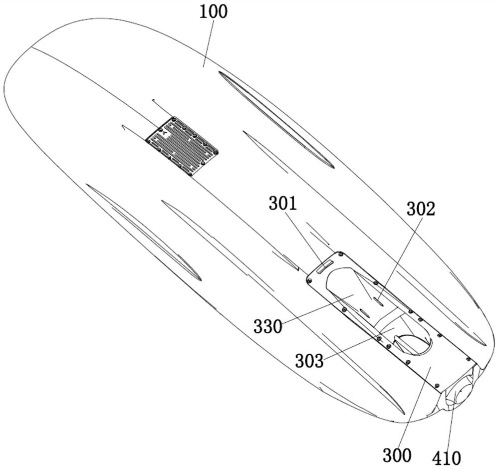
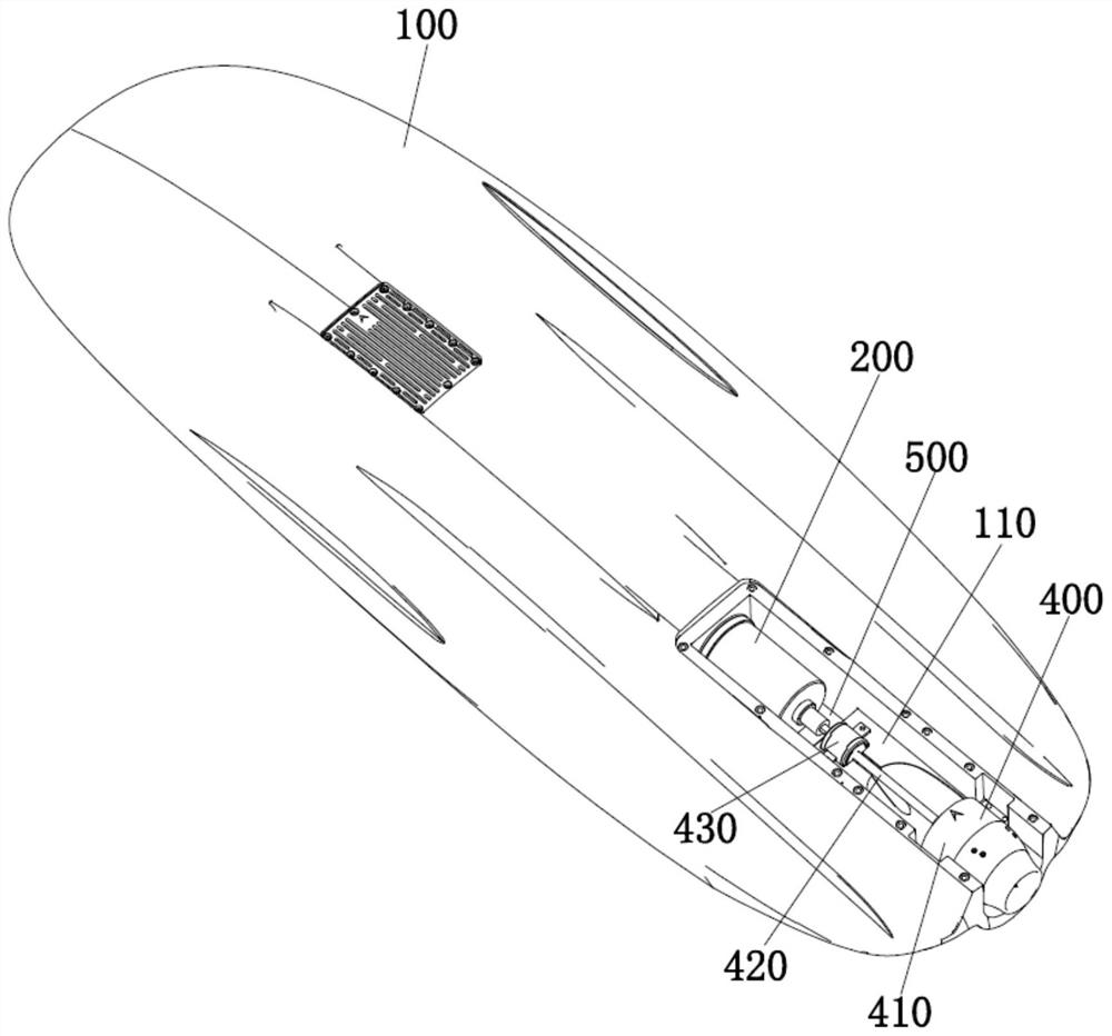
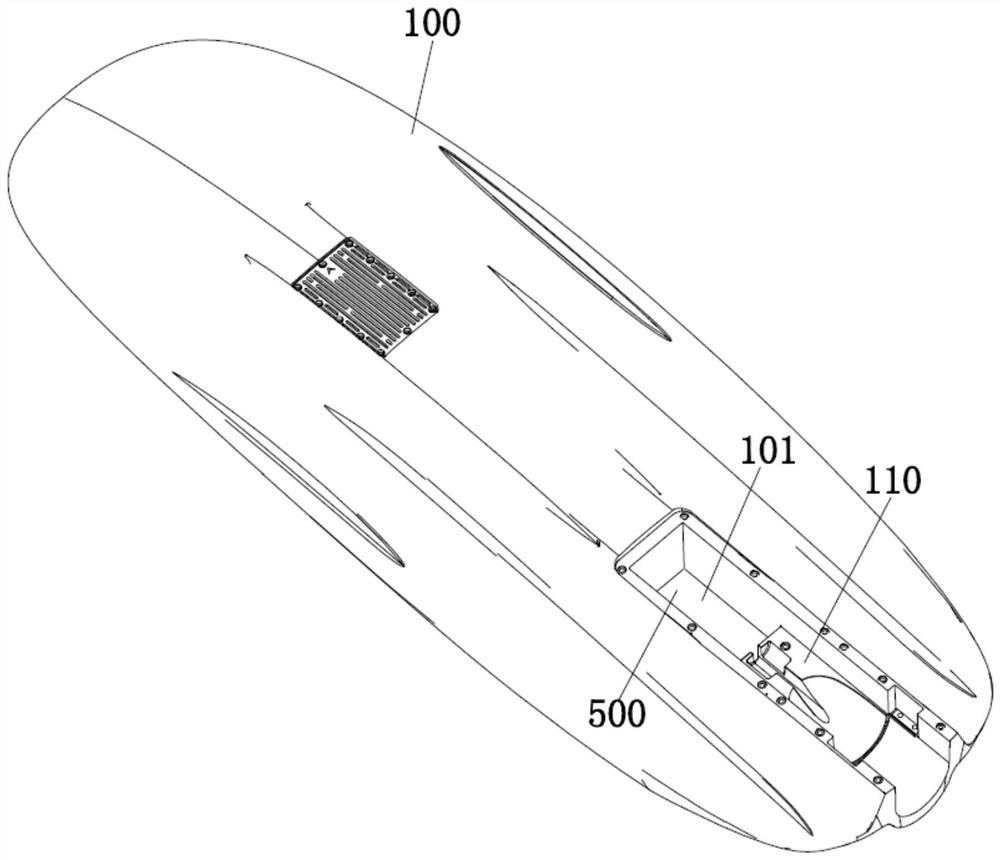
[0028] This embodiment relates to a surfboard jet pump structure with rapid heat dissipation effect, such as Figure 1-5 As shown, the bottom plate 100 of the surfboard is provided with an installation groove 101, and the jet pump structure is arranged in the installation groove 101, and the jet pump structure includes: a power source 200, a propeller assembly 400 and a main channel bottom cover 300.

[0029] Specifically, such as Figure 1-5 As shown, the power source 200 is fixedly installed in the mounting groove 101 on the side away from the tail of the surfboard, and the power source 200 is used to drive the propeller assembly 400 to move the surfboard. The propeller assembly 400 is fixedly installed in the installation groove 101 and fixedly assembled with the power output shaft of the power source 200 . The propeller assembly 400 is used to propel the water flow to the opposite side of the surfboard, so as to propel the surfboard to move by reverse thrust. The bottom ...

Embodiment 2

[0041] The difference between this embodiment and embodiment 1 mainly lies in, as Figure 6 As shown, in this embodiment, the bottom cover plate 300 of the sprue includes: a fixed A plate 340 and a fixed B plate 350 . The fixed A plate 340 is assembled with the side of the installation groove 101 away from the propeller assembly 400 , and the fixed A plate 340 is used to form the installation cavity 500 in combination with the installation table 110 and the installation groove 101 . The fixed B plate 350 is assembled with the side of the installation groove 101 close to the propeller assembly 400 . Dividing the main channel bottom cover 300 into two parts for marble assembly not only avoids the situation that the entire main main channel bottom cover 300 needs to be completely replaced due to damage to any one of the fixed A plate 340 or the fixed B plate 350, but also facilitates Separate access to power source 200 and to screw assembly.


PUM


Abstract

The invention discloses a surfboard spray pump structure with a rapid heat dissipation effect, and relates to the technical field of surfboards. A mounting groove is formed in a bottom plate of a surfboard, the spray pump structure is arranged in the mounting groove, and the spray pump structure comprises a power source fixedly mounted at one side, far away from the tail part of the surfboard, inthe mounting groove, a propeller assembly fixedly mounted in the mounting groove, fixedly assembled with a power output shaft of the power source and used for propelling water flow to one side opposite to the advancing direction of the surfboard, and a main flow channel bottom cover plate. The main flow channel bottom cover plate is arranged at a groove opening of the mounting groove, fixedly assembled with the mounting groove and used for shielding and protecting the power source, and when the surfboard moves, the main flow channel bottom cover plate is further used for achieving exchange between a cavity where the power source is located and external water flow so as to cool the power source. According to the technical scheme, the surfboard spray pump structure has the advantages of being simple in structure, ingenious in design, good in heat dissipation effect and long in service life.

Description

technical field [0001] The invention relates to the technical field of surfboards, in particular to a surfboard jet pump structure with rapid heat dissipation effect. Background technique [0002] Surfing is popular for its thrills and effective physical exercise. Ordinary surfboards can only be used by the thrust of wind and waves. When there is no wind and waves or the wind and waves are small, the surfboard will lose its due utility. In order to realize surfing that can be enjoyed when there is no wind or waves or when the wind and waves are small, there is already a kind of power surfboard in the prior art. [0003] Existing power surfboards generally include a hull, a jet pump structure, etc. The jet pump structure generally uses a motor to drive the propeller to rotate, thereby driving the water to move backwards, so that the surfboard provides the power for surfing on the water with the reverse thrust of the water, as the core component of the power The jet pump str...

Claims


Application Information

Patent Timeline
Patent Type & Authority Applications(China)
IPC IPC(8): B63B32/10B63B32/40B63H1/14B63H11/04
CPCB63H1/14B63H11/04B63B32/10B63B32/40
Inventor 马季骏
Owner SHENZHEN TIANYUN GEEK TECH CO LTD
Why Eureka
Try Eureka