Cloth feeding mechanism with automatic parking function for textile equipment

A technology of textile equipment and feeding mechanism, applied in the field of cloth feeding mechanism for textile equipment, can solve the problems of loose cloth, changing the rotation speed of the roller by the transmission rate, affecting the tightness of the cloth, etc., so as to avoid waste, ensure the tightness, The effect of simplifying the loading and unloading structure

Active Publication Date: 2020-12-18
杭州康泰纺织品有限公司
View PDF9 Cites 1 Cited by
  • Summary
  • Abstract
  • Description
  • Claims
  • Application Information

AI Technical Summary

Problems solved by technology

[0004] The purpose of the present invention is: in order to solve the existing shortcomings in the process of using the cloth feeding mechanism for textile equipment, the rollers for cloth winding are mostly completed by directly using bolts or clamping methods. It is difficult to connect with the driving equipment for the installation of the cylinder, and because the feeding mechanism has a certain transmission distance from the textile equipment, when it is necessary to temporarily replace other fabrics for production, it is difficult to quickly rewind the unused fabric that has been separated from the roller. On the fabric guide roller, and during the transmission of the fabric, the roller is prone to change the rotation speed of the roller more frequently due to the frustration caused by the uneven transmission rate during the stress process of the fabric, resulting in the loosening of the fabric on the roller. Seriously affect the degree of tension required for cloth transmission, and easily affect the processing effect of textile equipment on the cloth, and a cloth feeding mechanism for textile equipment with automatic parking function is proposed

Method used


Image

  • Cloth feeding mechanism with automatic parking function for textile equipment
  • Cloth feeding mechanism with automatic parking function for textile equipment
  • Cloth feeding mechanism with automatic parking function for textile equipment

Examples


Embodiment Construction

[0039] The technical solutions in the embodiments of the present invention will be clearly and completely described below in conjunction with the accompanying drawings in the embodiments of the present invention. Apparently, the described embodiments are only some, not all, embodiments of the present invention. Based on the embodiments of the present invention, all other embodiments obtained by persons of ordinary skill in the art without creative efforts belong to the protection scope of the present invention.

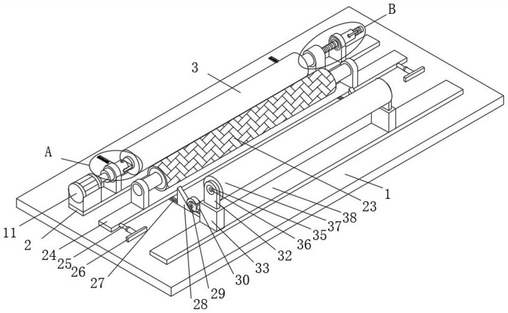
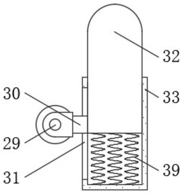
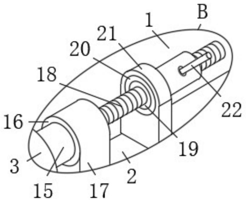
[0040] see Figure 1-6 , the present invention provides a technical solution: a cloth feeding mechanism for textile equipment with automatic parking function, including a base 1, the top of the base 1 is fixedly connected with a first movable seat 2, and the top of the first movable seat 2 is arranged There is a cloth guide roller 3, and the end of the cloth guide roller 3 is provided with a first insertion groove 34, and a first insertion handle 4 is inserted into on...


PUM


Abstract

The invention discloses a cloth feeding mechanism with an automatic parking function for textile equipment, and belongs to the technical field of textile equipment. The cloth feeding mechanism comprises a base, and the top of the base is fixedly connected with a first movable seat. According to the cloth feeding mechanism, through mutual cooperation of a cloth guide roller, a first spring, a second spring, a hydraulic cylinder, a speed limiting roller, a cloth conveying roller, a sliding block, a sliding groove, a first inserting connecting handle, a first inserting connecting groove, a fixingsleeve, a lifting base, a guide wheel, a wedge-shaped plate and a motor, the loading and unloading structure of the cloth conveying roller is simplified, and unused cloth can be rolled on the cloth guide roller again. The tightness of the cloth on the cloth guide roller can be guaranteed, waste is avoided, the rotating speed of the cloth conveying roller can be automatically changed along with the feeding speed of the textile equipment, and the situation that the rotating speed of the cloth guide roller is frequently changed due to bumping caused by the fact that the conveying speed of the cloth is uneven in the stress process is avoided; and the tightness of the fed cloth in the working process of the textile equipment is effectively ensured.

Description

technical field [0001] The invention belongs to the technical field of textile equipment, in particular to a cloth feeding mechanism for textile equipment with an automatic stop function. Background technique [0002] The original meaning of textile is taken from the general term of spinning and weaving, but with the continuous development and improvement of the textile knowledge system and subject system, especially after the emergence of non-woven textile materials and three-dimensional composite weaving technologies, it is not only the traditional hand spinning And weaving, also including non-woven technology, modern three-dimensional weaving technology, modern electrostatic nano-netting technology and other clothing, industrial and decorative textiles. Therefore, modern textile refers to a variety of fibers or fiber aggregates. Scale structure processing technology, ancient Chinese textile and printing and dyeing technology has a very long history. As early as in the pri...

Claims


Application Information

Patent Timeline
Patent Type & Authority Applications(China)
IPC IPC(8): B65H23/06B65H20/02B65H18/10B65H18/02
CPCB65H23/06B65H20/02B65H18/10B65H18/028
Inventor 陈苏莲
Owner 杭州康泰纺织品有限公司
Why Eureka
Try Eureka