Electric single-beam crane

A crane and single-girder technology, applied in the direction of load block, load suspension components, transportation and packaging, etc., can solve the problems of large-scale equipment damage, violent shaking, large-scale equipment shaking, etc.

Inactive Publication Date: 2020-12-18
安徽奋途建设工程有限公司
View PDF1 Cites 6 Cited by
  • Summary
  • Abstract
  • Description
  • Claims
  • Application Information

AI Technical Summary

Problems solved by technology

[0004] In the process of realizing the present invention, the inventor found that at least the following problems in the prior art have not been solved: 1. The position of large-scale equipment cannot be accurately positioned when lifting, and when the lifting position is inaccurate, large-scale equipment cannot The moment it leaves the ground, it will shake violently, which will cause damage to the large-scale equipment; 2. The crane will shake and even hit the wall when moving the large-scale equipment; 3. The electric hoist moves laterally to both ends of the main beam. It is likely to hit the end beam and the wall at the boundary position, causing severe shaking of large instruments and equipment

Method used


Image

  • Electric single-beam crane
  • Electric single-beam crane
  • Electric single-beam crane

Examples


Embodiment approach

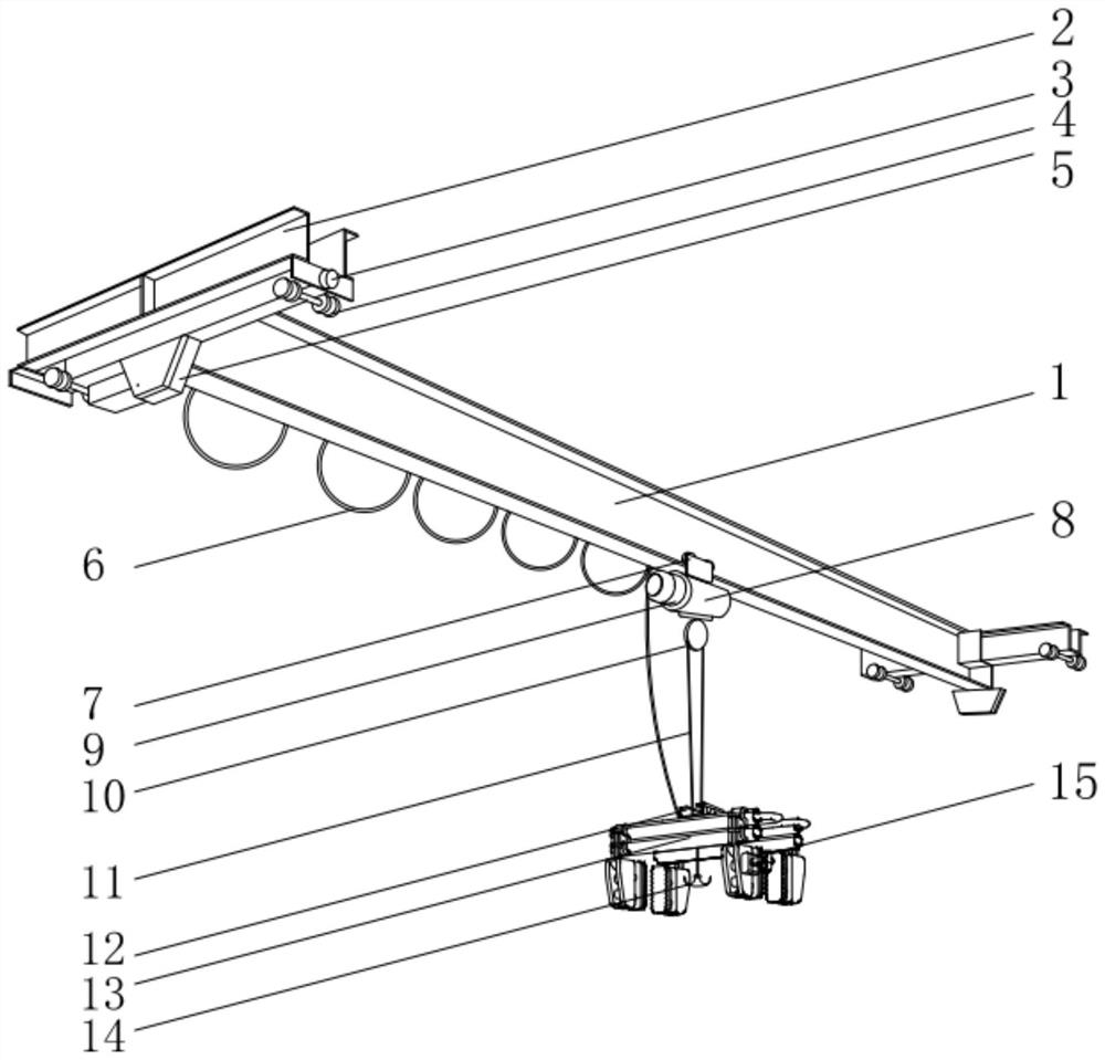
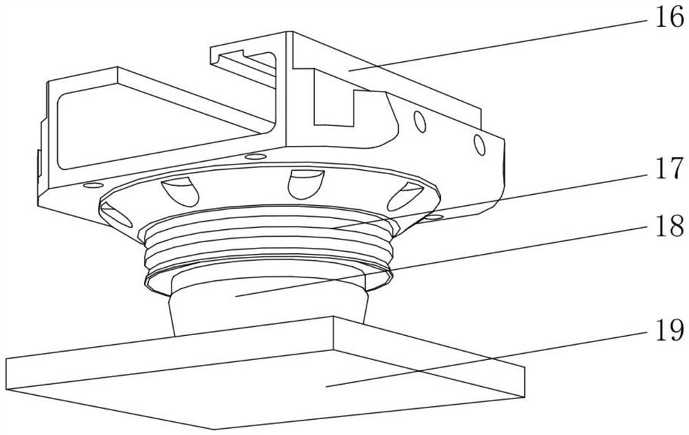
[0038] As an embodiment of the present invention, the electric single girder crane is characterized in that: the rubber air spring 9 includes a cover plate 91, an aluminum alloy flange 93, an air bag 94, a fixing plate 95 and a waist ring 92 The outer surface of the lower end of the cover plate 91 is fixedly equipped with an aluminum alloy flange 93, the outer surface of the lower end of the aluminum alloy flange 93 is fixedly installed with an airbag 94, and the outer surface of the lower end of the airbag 94 is fixedly connected with a fixed The middle position between the plate 95 and the airbags 94 is fixedly connected with a waist ring 92, wherein the core component of the rubber air spring 9 is the airbag 94, and the airbag 94 is filled with compressed air in a flexible rubber capsule, and the air can be compressed The elastic effect is realized by the cover plate 91, the stress point where the airbag 94 contacts with the cushioning air cushion 5, the aluminum alloy flang...


PUM


Abstract

The invention provides an electric single-beam crane. The electric single-beam crane comprises a main beam, end beams are fixedly mounted on the outer surfaces of the two sides of the main beam, operation signal lamps are fixedly mounted on the outer surfaces of one sides of the end beams, and pulleys are fixedly mounted on the two sides of the outer surfaces of the lower ends of the end beam. Buffer air cushions are fixedly mounted in the middle of the outer surfaces of the lower ends of the end beams, a cable is movably connected to the outer surface of the lower end of the main beam, a running trolley is slidably connected to the outer surface of the lower end of the main beam, an electric hoist is fixedly mounted at the lower end of the running trolley, and rubber air springs are arranged on the outer surfaces of the two sides of the electric hoist. According to the electric single-beam crane, the hoisting position and the falling point position can be accurately positioned when large instruments and equipment are hoisted and moved, stable movement and accurate direction of the hoisting and falling points are ensured, the risk of wall collision is avoided, and the stability ofthe large instruments and equipment is ensured.

Description

technical field [0001] The invention relates to the technical field of cranes, in particular to an electric single-girder crane. Background technique [0002] The electric single-girder crane is a lifting device that is placed horizontally over the workshop, warehouse and stockyard for material lifting. The bridge frame of the electric single-girder crane runs longitudinally along the rails laid on the elevated sides on both sides, which can make full use of the space under the bridge frame for hoisting. It is the most widely used and the largest number of hoisting machinery, mainly composed of electric hoist, metal structure, cart running mechanism, power feeding device and electrical device. [0003] The existing patent (notification number: CN210340100U) is an energy-saving electric single-girder crane, including an I-shaped main beam, an end beam, a walking track beam, a walking trolley, an electric hoist, and a guiding pressure-dividing mechanism; Both sides are equipp...

Claims


Application Information

Patent Timeline
Patent Type & Authority Applications(China)
IPC IPC(8): B66C11/06B66C11/18B66C13/06B66C11/26B66C13/16B66C1/44
CPCB66C1/445B66C11/06B66C11/18B66C11/26B66C13/063B66C13/16
Inventor 徐建军王旭
Owner 安徽奋途建设工程有限公司
Why Eureka
Try Eureka