Siphon engineering design

An engineering design and siphon technology, which is applied in siphon pipes, sea area engineering, water conservancy projects, etc., can solve the problems of losing siphon, not being able to prevent the release of air in the water, and the siphon device does not consider the eddy current problem, etc., and achieve the effect of a reliable drainage method

Active Publication Date: 2020-12-18
浙江思科瑞真空技术有限公司
View PDF10 Cites 4 Cited by
  • Summary
  • Abstract
  • Description
  • Claims
  • Application Information

AI Technical Summary

Problems solved by technology

[0007] But its disadvantages are: under the action of the vacuum pump, the dissolved gas in the water will be released, so that the vacuum pump must be kept running all the time. A Venturi effect can continuously absorb and drain water-but it loses the value of siphon
[0009] But its disadvantage is: the siphon device does not consider the eddy current problem, and th

Method used


Image

  • Siphon engineering design
  • Siphon engineering design
  • Siphon engineering design

Examples


Embodiment Construction

[0055]The preferred features of the present invention will be described in detail below by way of examples and in conjunction with the accompanying drawings. It should be recognized that, obviously, the accompanying drawings in the following description are only some embodiments of the present invention. For those skilled in the art , on the premise of not paying creative efforts, other embodiments can also be obtained according to the principle description of the context and the extension of these embodiment diagrams.

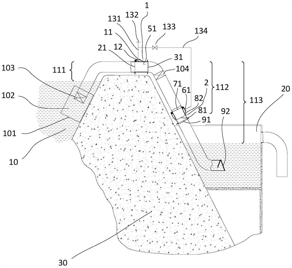
[0056] Such as figure 1 Shown, a kind of siphon engineering design of the present invention, on the siphon pipeline road on the embankment 30, deceleration tube 102, anti-eddy current grid 103 are installed, and siphon degasser 1, siphon degasser are installed on the starting point of gravitational potential energy action The liquid inlet 21 of 1 is connected with the siphon upper water pipe. There is a gap 51 and a cavity 12 in the siphon degasser 1, so that ...


PUM


Abstract

The invention discloses a siphon engineering design, belongs to the technical field of siphon engineering designs in water conservancy technologies, and aims to establish an economical flood control and flood discharge engineering design, a slope drainage design, a building drainage design, a water resource utilization design and an industrial liquid energy recycling design. A siphon degasser, a siphon mixer and a siphon vacuum pump system are mounted on a siphon pipeline, so that the siphon process is achieved economically.

Description

technical field [0001] The invention belongs to the technical field of siphon engineering design in water conservancy technology, and in particular relates to a siphon engineering design. Background technique [0002] Among the existing flood control and flood discharge methods for rivers, lakes, reservoirs, etc., most of them use flood discharge methods such as spillway tunnels, spillways (dams) or flood gates, and the technology used for flood control is only through building or strengthening flood control dikes. To be done. But no matter what kind of flood control and flood discharge method, the engineering volume and cost of its construction are very large. And limited by the amount of work and the difficulty of construction, the flood discharge methods are almost always designed in a certain area. However, a very big disadvantage of this method is that in a certain area, the existing flood discharge methods are carried out. During flood discharge, the energy generated...

Claims


Application Information

Patent Timeline
IPC IPC(8): E02B8/06E03F1/00E03F3/04E03F5/20F04F10/00F04F5/04F04F5/44F04B39/06
CPCE02B8/06E03F1/006E03F3/04E03F5/20F04F10/00F04F5/04F04F5/44F04B39/06
Inventor 李军徐东旭
Owner 浙江思科瑞真空技术有限公司
Why Eureka
Try Eureka