Squeeze film damper with novel outer ring structure

A technology of extruding oil film damping and damper, which is applied in the direction of spring/shock absorber, vibration suppression adjustment, mechanical equipment, etc., can solve the problems of high maintenance cost, increase the complexity of damper structure, etc., and achieve the reduction of oil film stiffness and structure Simple, the effect of increasing the working area

Active Publication Date: 2020-12-18
SHENYANG AEROSPACE UNIVERSITY
View PDF6 Cites 0 Cited by
  • Summary
  • Abstract
  • Description
  • Claims
  • Application Information

AI Technical Summary

Problems solved by technology

The above improvements are all achieved through the external damper structure and control structure, which increases the complexity of the damper structure
Due to the compact size of the aero-engine, higher requirements are placed on the structural size design and assembly of the damper, and there will be problems such as high maintenance costs in long-term use

Method used


Image

  • Squeeze film damper with novel outer ring structure
  • Squeeze film damper with novel outer ring structure
  • Squeeze film damper with novel outer ring structure

Examples


Embodiment 1

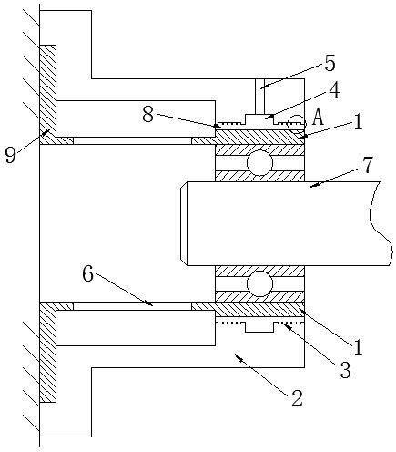
[0033] like Figure 1~6 As shown, a squeeze film damper with a novel outer ring structure of the present invention includes a fixed outer ring 2 of the damper, a fixed elastic support base 9 and an inner ring of the damper installed on the inner ring of the outer ring 2 of the damper 1. The outer ring 2 of the damper is fixed on the frame. The outer ring 2 of the damper is a ring structure with a round hole inside. The inner ring 1 of the damper is a ring structure and is installed inside the outer ring 2 of the damper. The inner ring 1 is concentric with the outer ring 2 of the damper.

[0034] The elastic support base 9 and the damper outer ring 2 are affixed to the frame together, and the damper inner ring 1 is connected to the elastic support base 9 through the elastic support 6, and the elastic support 6 is a cage structure, so The elastic support 6 is provided with several cage bars along the circumferential direction, and the two ends of the cage bars are respectively ...

Embodiment 2

[0047] like Figure 1~7 As shown, the difference between this embodiment and embodiment 1 is:

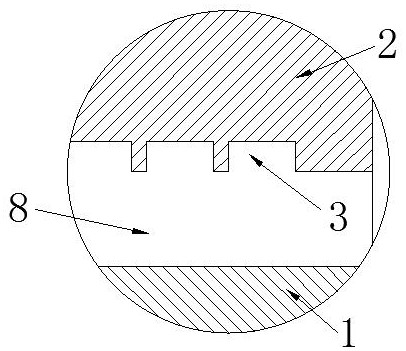
[0048] The oil film counterbore 3 is a circular counterbore, and the circular hole structure is simpler than the honeycomb structure, and the processing technology is less difficult.

[0049] The diameter of the oil film counterbore 3 is 1mm, and the depth of the oil film counterbore 3 is 0.1mm. A plurality of oil film counterbores 3 are arranged in a straight line in the axial direction of the damper outer ring 2 and arranged in a staggered manner in the circumferential direction of the damper outer ring 2 .

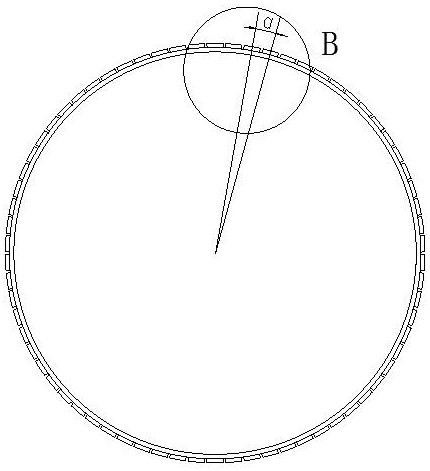
[0050] The distance h between the centers of the adjacent oil film counterbore 3 along the axial direction of the damper outer ring 2 is 1.08mm, and the linear distance d between the centers of the adjacent oil film counterbore 3 in the circumferential direction is 0.93mm. Any two phases in the circumferential direction The included angle a between the center of the adjacen...


PUM


Abstract

The invention relates to a squeeze film damper with a novel outer ring structure. The squeeze film damper comprises a fixed damper outer ring, a fixed elastic support base and a damper inner ring arranged on the inner ring of the damper outer ring, wherein the damper inner ring is connected with the elastic support base through an elastic support, and a rotor is arranged on the inner ring of the damper inner ring; an oil film is filled between the inner ring of the damper outer ring and the outer ring of the damper inner ring; an oil supply hole communicated with the oil film is arranged on the damper outer ring; a plurality of oil film counter bores are evenly distributed on the inner ring of the damper outer ring in the circumferential direction; and lubricating oil entering the oil filmcan immediately fill the oil film counter bores under the action of vortexes existing in the oil film counter bores; the vortex effect in the oil film counter bores can hinder the flow of the lubricating oil, completeness of the oil film is guaranteed, more vibration energy can be absorbed through the vortex effect of the oil film counter bores, oil film damping is improved, oil film rigidity isreduced, and stability of a rotor system is improved.

Description

technical field [0001] The invention relates to the technical field of squeeze oil film dampers, in particular to a squeeze oil film damper with a novel outer ring structure. Background technique [0002] The unbalanced force generated by the gravity of the rotor system, manufacturing and assembly errors and other unbalanced factors of the aero-engine and the rotor passing through the critical speed often cause strong vibration of the rotor system, resulting in a decrease in the working stability of the engine. According to statistics, the aero-engine Structural strength failures related to vibration account for more than 90% of the total failures. In order to reduce the vibration of the rotor system, a squeeze oil film damper is usually used at the rotor support to suppress the vibration of the rotor system. [0003] Squeeze oil film damper has the advantages of simple structure, good vibration reduction effect, effectively reducing rotor vibration, reducing external force...

Claims


Application Information

Patent Timeline
Patent Type & Authority Applications(China)
IPC IPC(8): F16F15/16F16F15/167
CPCF16F15/16F16F15/167
Inventor 周海仑张钰奇陈玺孙丹艾延廷
Owner SHENYANG AEROSPACE UNIVERSITY
Why Eureka
Try Eureka