
Plate stacking equipment and sintering production line

A code board and equipment technology, which is applied in the field of code board equipment and sintering production lines, can solve the problems of difficult to guarantee product quality and production capacity, poor consistency, and high product scrap rate, so as to avoid product defects, improve code board efficiency, and ensure quality. Effect

Pending Publication Date: 2020-12-18
MOBILE ANTENNA TECH SHENZHEN +5
View PDF0 Cites 2 Cited by
  • Summary
  • Abstract
  • Description
  • Claims
  • Application Information

AI Technical Summary

Problems solved by technology

[0004] This application provides a coding board equipment and a sintering production line to solve the problems of heavy workload, high product scrap rate and poor consistency of manual coding boards, which make it difficult to guarantee product quality and production capacity

Method used


Image

  • Plate stacking equipment and sintering production line
  • Plate stacking equipment and sintering production line
  • Plate stacking equipment and sintering production line

Examples


Embodiment Construction

[0035] In order to make the purposes, technical solutions and advantages of the embodiments of the present application clearer, the technical solutions in the embodiments of the present application will be clearly and completely described below in conjunction with the drawings in the embodiments of the present application. Obviously, the described embodiments It is a part of the embodiments of this application, not all of them. Based on the embodiments in this application, all other embodiments obtained by persons of ordinary skill in the art without creative efforts fall within the protection scope of this application.

[0036] In the description of the embodiments of the present application, the terms "first" and "second" are used for description purposes only, and cannot be understood as indicating or implying relative importance or implicitly indicating the quantity of indicated technical features. Thus, the features defined as "first" and "second" may explicitly or implic...


PUM


Abstract

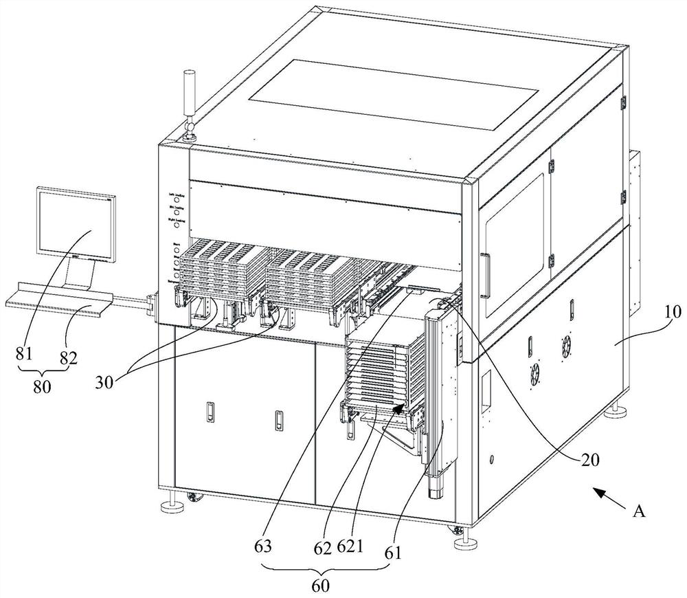
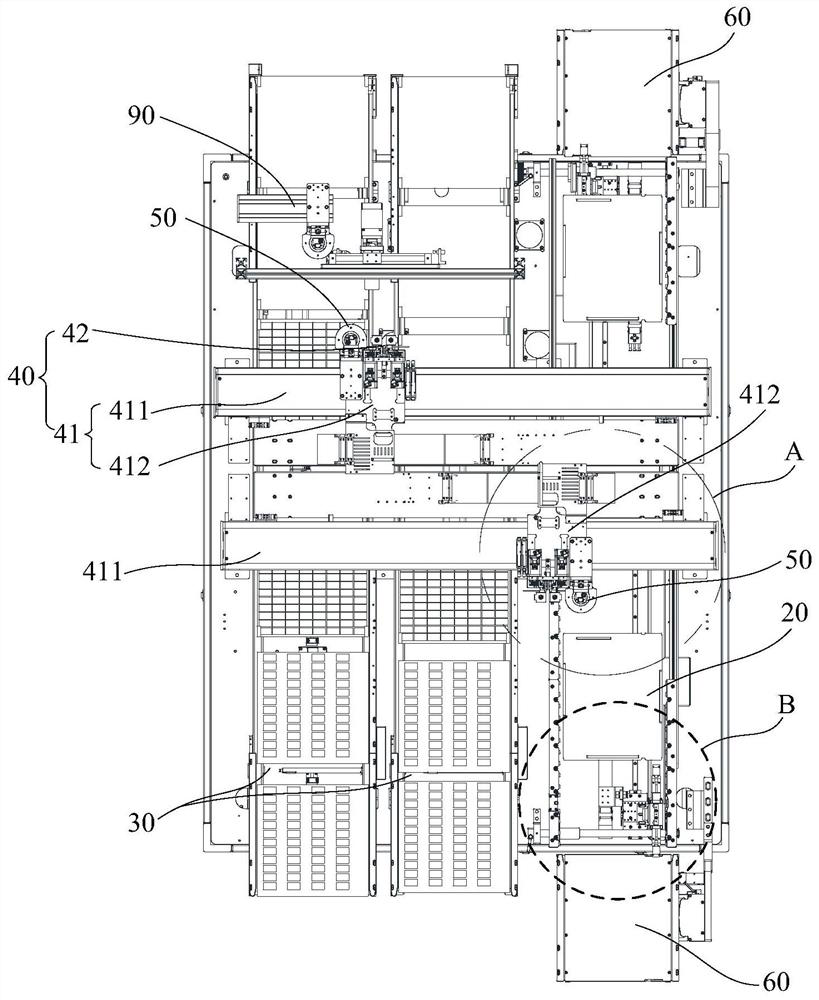
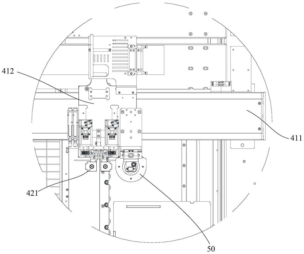
The invention provides plate stacking equipment and a sintering production line, wherein the plate stacking equipment comprises a rack, a first conveying mechanism, a second conveying mechanism and aplate stacking mechanism; the first conveying mechanism and the second conveying mechanism are arranged on the rack side by side and used for conveying sintering trays respectively; the plate stackingmechanism comprises a sliding assembly and a grabbing assembly arranged on the sliding assembly; the sliding assembly straddles the first conveying mechanism and the second conveying mechanism; the sliding assembly is used for driving the grabbing assembly to move between the first conveying mechanism and the second conveying mechanism; and the grabbing assembly is used for grabbing target objects conveyed on the sintering trays and stacking the target objects to the sintering trays on the other conveying mechanism under driving of the sliding assembly. According to the plate stacking equipment and the sintering production line provided by the invention, the plate stacking efficiency and the uniformity of blanks after plate stacking can be improved, the sintering quality is ensured, and bad product caused by human factors is avoided.

Description

technical field [0001] The invention relates to the technical field of firing process equipment, in particular to a code plate equipment and a sintering production line. Background technique [0002] Ceramic dielectric filters are widely used in filtering radio frequency signals due to their low loss, high dielectric constant, small frequency temperature coefficient and thermal expansion coefficient, and high power tolerance. Especially with the advent of the era of 5th generation mobile networks (5G), the demand for ceramic dielectric filters is gradually increasing. [0003] At present, when firing filters, the sintering process of the pusher furnace is to use manual stacking, stacking and loading and unloading. However, due to the small size of the ceramic dielectric filter itself, the single production quantity is large, and there are problems such as large workload, high product scrap rate and poor consistency caused by manual code boards, which makes it difficult to g...

Claims


Application Information

Patent Timeline
Patent Type & Authority Applications(China)
IPC IPC(8): F27B17/00F27D3/00F27D5/00F27D19/00B65G61/00B65G57/04B65G57/16
CPCB65G57/04B65G57/16B65G61/00B65G2201/02F27B17/0033F27D3/0021F27D3/06F27D5/0012F27D19/00F27D2019/0059
Inventor 蒋伟华胡孟夏梁小健顾国治黄庆焕
Owner MOBILE ANTENNA TECH SHENZHEN
Learn More