Moving object three-dimensional measurement method based on color fringe projection

A technology of color stripes and moving objects, applied in the field of 3D measurement, can solve the problem of slowing down the 3D measurement speed, and achieve the effect of avoiding color crosstalk, improving accuracy and fast measurement speed.

Active Publication Date: 2020-12-18
ANHUI AGRICULTURAL UNIVERSITY
View PDF11 Cites 5 Cited by
  • Summary
  • Abstract
  • Description
  • Claims
  • Application Information

AI Technical Summary

Problems solved by technology

[0004] For example: Estimate the motion information of the object through feature point matching, and compensate the measurement error caused by the motion, but this method requires the object to have obvious features and be a rigid object (Optics Express, 2013, 21 (25): 30610-22; Optics Communications ,2019,438:61-6); use additional stripes to compensate

Method used


Image

  • Moving object three-dimensional measurement method based on color fringe projection
  • Moving object three-dimensional measurement method based on color fringe projection
  • Moving object three-dimensional measurement method based on color fringe projection

Examples


Embodiment 1

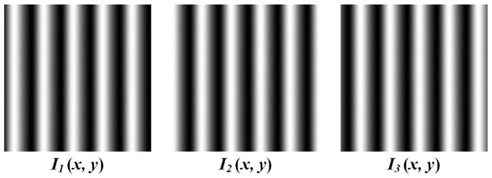
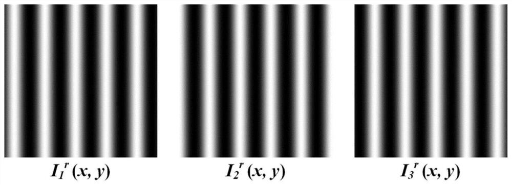
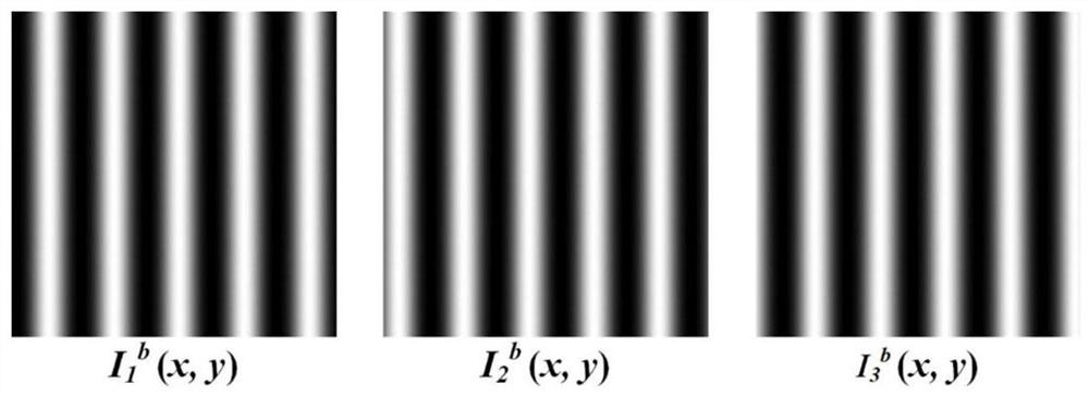
[0074] Assuming that the measured object is in a state of uniform motion, and the additional phase shift introduced by the motion is represented by ε(x,y), the intensity distribution of the sine fringes in the red channel and the cosine fringes in the blue channel is expressed as:

[0075]

[0076]

[0077]

[0078]

[0079]

[0080]

[0081] According to the literature Optics Express, 2018, 26(26): 34224-35, the absolute phase error ΔΦ of the final calculated sinusoidal fringes can be deduced r Absolute phase error ΔΦ of (x,y) and cosine fringes b (x,y) can be approximately equal to:

[0082]

[0083]

[0084] Theoretically, the absolute phase Φ of a sinusoidal fringe r (x,y) and the absolute phase Φ of the cosine fringe b (x, y) are equal, that is, the following relationship exists:

[0085] Φ r (x,y)=Φ b (x,y)=Φ o (x,y)

[0086] Obviously, the absolute phase error ΔΦ of the sinusoidal fringe r Absolute phase error ΔΦ of (x,y) and cosine fring...

Embodiment 2

[0090] Assuming that the measured object is in a state of non-uniform motion, and the additional phase shift introduced by the motion is represented by ε(x,y), the intensity distribution of the sine fringes in the red channel and the cosine fringes in the blue channel can be re-expressed as:

[0091]

[0092]

[0093]

[0094]

[0095]

[0096]

[0097] Such as Figure 6 As shown, the absolute phase Φ of the sinusoidal fringe under non-uniform motion and ε(x,y)=0.3 is given r (x,y), the absolute phase of the cosine fringe Φ b (x, y), the schematic diagram of the average phase Φ(x, y), and their error ΔΦ r (x,y), ΔΦ b (x,y), ΔΦ(x,y) schematic diagram. It can also be seen that the average phase error ΔΦ(x,y) is much smaller than the absolute phase error ΔΦ of the sinusoidal fringes r Absolute phase error ΔΦ of (x,y) and cosine fringes b (x,y).


PUM


Abstract

The invention discloses a moving object three-dimensional measurement method based on color fringe projection. The method comprises the steps: S1, establishing a fringe projection three-dimensional measurement system; S2, projecting the color stripes to the surface of the moving object by a projector, and generating deformed color stripes through the modulation effect of the surface of the movingobject; S3, synchronously collecting all deformed color stripes by a camera, and extracting sine stripes in a red channel and cosine stripes in a blue channel; S4, respectively calculating a truncation phase of the sine fringe and a truncation phase of the cosine fringe by using a three-step phase shift algorithm; S5, performing phase unwrapping on the sine fringe truncation phase and the cosine fringe truncation phase to obtain a sine fringe absolute phase and a cosine fringe absolute phase; S6, calculating the average phase of the sine fringe absolute phase and the cosine fringe absolute phase, and eliminating the phase error caused by the motion of the object; and S7, converting the average phase into height information, and reconstructing the three-dimensional shape of the moving object.

Description

technical field [0001] The invention belongs to the technical field of three-dimensional measurement, in particular, the invention relates to a method for three-dimensional measurement of a moving object based on color fringe projection. Background technique [0002] The fringe projection three-dimensional measurement technology has the advantages of non-contact, high precision, fast speed, and simple structure. It is widely used in industrial inspection, biomedicine, agricultural engineering, product reverse development and other fields. The traditional fringe projection system mainly includes two parts: a projector and a camera. The projector is responsible for projecting the fringe onto the surface of the object, and the camera is responsible for collecting the modulated fringe of the object. By extracting the phase distribution of the modulated fringes, the three-dimensional shape of the object can be reconstructed. [0003] At present, the phase shift method and the Fo...

Claims


Application Information

Patent Timeline
IPC IPC(8): G01B11/25
CPCG01B11/254
Inventor 王玉伟刘路唐七星奚冬冬陈向成
Owner ANHUI AGRICULTURAL UNIVERSITY
Why Eureka
Try Eureka