Novel steel core ice melting insulated wire and ice melting system and method thereof

A technology of insulated wires and steel cores, applied in the direction of insulated conductors, insulated cables, conductors, etc., can solve the problems of limited application range, small equipment footprint, large capacity of ice-melting power supply, etc., to expand the scope of application and reduce ice-melting The effect of current

Inactive Publication Date: 2020-12-18
永州电力勘测设计院有限公司
View PDF3 Cites 3 Cited by
  • Summary
  • Abstract
  • Description
  • Claims
  • Application Information

AI Technical Summary

Problems solved by technology

[0010] It can also be seen from the above table that, in addition, the 35kV voltage level of AC ice melting has a relatively large ice melting distance, which exceeds the length of the mainstream line of the existing power grid. The length is appropriate, but the capacity of the ice-melting power supply required is very large. Taking the common 300-section wire in the power grid as an example, the apparent power of ice-melting wire of 38km reaches 80MVA, far exceeding the capacity of a common three-winding 110kV transformer. Therefore, When melting ice at a voltage level of 35kV for large cross-section, double-split conductors or long lines, only the 220kV substation with a transformation ratio of 220 / 110 / 35kV main transformer can provide ice-melting power. This kind of substation is very rare in the power grid. Therefore, the scope of application is very limited
[0011] Voltage regulation of ice-melting transformer AC ice-melting By setting an adjustable gear ice-melting transformer in the substation, the ice-melting voltage can be flexibly adjusted according to the length of the line and the type of wire, which can effectively solve the problem of the limitation of the ice-melting distance, but for longer The larger the transmission line and the larger the conductor cross-section, the greater the ice-melting load. Therefore, the size and area of ​​the ice-melting transformer are very large. The installation location of the ice-melting transformer is not considered in the general design of the built substation and the new substation. Most substations do not have the conditions to install ice-melting transformers
[0012] Although DC icing has the advantages of long and flexible icing distance, small equipment footprint, small capacity of icing power supply to be configured, no need to match line impedance and load transfer, but DC icing cannot achieve three-phase simultaneous icing , and the DC power supply is very expensive, and the number of DC ice-melting devices that can be configured is small

Method used


Image

  • Novel steel core ice melting insulated wire and ice melting system and method thereof
  • Novel steel core ice melting insulated wire and ice melting system and method thereof
  • Novel steel core ice melting insulated wire and ice melting system and method thereof

Examples


Embodiment 1

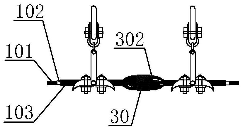
[0029] see figure 1 , this embodiment provides a new type of steel core ice-melting insulated wire, the new type of steel core ice-melting insulated wire includes a steel core 101, an outer layer of aluminum stranded wire 103 and an insulating wire between the steel core and the outer layer of aluminum stranded wire layer 102, the two ends of the steel core are electrically connected to the outer layer of aluminum strands.

[0030] Specifically, according to the laying of power grid lines, when the laying range is large, multiple wires need to be connected. In this embodiment, two adjacent wires are connected through intermediate joints 30, and the intermediate joints 30 respectively connect The two steel cores 101 and the aluminum stranded wires 103 are electrically connected, and the steel core 101 and the aluminum stranded wires 103 are insulated by crimping the insulating layer 302 . The specific structure can refer to the pre-twisted wire suspension clamp structure for OP...

Embodiment 2

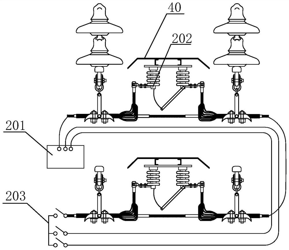
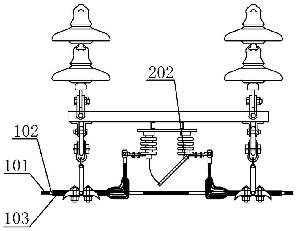
[0032] On the basis of Example 1, please refer to figure 2 and image 3 , the present embodiment provides a steel-core ice-melting insulated conductor ice-melting system, including an AC power supply 201, a steel-core insulation isolating switch 202 and a short-circuit knife switch 203, the aluminum strand of the conductor is disconnected, and the disconnection The steel core insulated isolating switch is connected, the short circuit switch is set at one end of the wire, and the AC power supply is connected to the other end of the wire.

[0033] Specifically, the steel core insulated isolating switch of this embodiment needs to be installed on the frame of the substation line outlet interval through insulators with the same insulation level as the line, or on a certain pole tower of the line. The line is equipotential, and it is at the floating potential when it is pulled apart, and the opening and closing operation is performed through the insulating rod.

[0034] Preferab...

Embodiment 3

[0037]On the basis of Embodiment 2, this embodiment provides an ice melting method of the ice melting system, specifically: when melting ice, open the steel core insulation isolating switch 202, close the short circuit knife switch 203, All the ice-melting currents from the AC power supply 201 flow through the steel core 101 to melt the ice.

[0038] Theoretical basis of the present invention:

[0039] According to the calculation formula of the melting current of the wire:

[0040]

[0041] In the formula: I r ——Icing current (A)

[0042] R 0 ——Wire resistance at 0°C (ohm / meter)

[0043] T r ——Icing time (hours)

[0044] Δt——the difference between the conductor temperature and the outside air temperature (°C)

[0045] g O ——The specific gravity of ice (generally 0.9 is taken as Yusong)

[0046] b—thickness of the ice layer, that is, the thickness of ice on each side of the ice (cm)

[0047] D——The outer diameter of the conductor after ice coating (cm)

[0048] R...


PUM


Abstract

The invention relates to an ice melting system of a novel steel core ice melting insulation wire, the wire comprises a steel core, an outer layer aluminum stranded wire and an insulation layer arranged between the steel core and the outer layer aluminum stranded wire, two ends of the steel core are electrically connected with the outer layer aluminum stranded wire, the aluminum stranded wire of the wire is disconnected, the disconnection position is connected with a steel core insulation isolation switch, a short-circuit knife switch is arranged at one end of the wire, and the alternating-current power supply is connected with the other end of the wire. And during ice melting, the steel core insulation isolation switch is switched off, the short-circuit knife switch is switched on, and icemelting is carried out by utilizing the ice melting current of the alternating-current power supply through the circulation of the steel core. By utilizing the high resistance of the wire steel core,the ice melting current and ice melting apparent power required by alternating current ice melting are reduced, and the application range of 35kV-voltage-grade alternating current wire ice melting isexpanded, so that the 110kV three-winding transformer substation can also be used as a 35kV alternating current ice melting power supply for melting ice, and the blank of 10kV alternating current icemelting is filled.

Description

technical field [0001] The invention relates to the technical field of power grid deicing, in particular to a novel steel core ice-melting insulated wire and its ice-melting system and method. Background technique [0002] In the ice and snow disaster, the power grid was seriously damaged, and the serious ice coating of the conductor was the main reason. Therefore, in addition to adopting specially designed towers and high-strength conductors in heavy ice areas according to historical meteorological data during the design and construction of the line, it is necessary to improve the anti-icing ability of the line. Ice-melting facilities have also been designed and supported, which use thermal effects to melt ice by passing large currents through conductors or overhead ground wires. [0003] At present, the ice-melting schemes can be divided into two categories: AC ice-melting and DC ice-melting according to different ice-melting power sources. According to the deicing volta...

Claims


Application Information

Patent Timeline
IPC IPC(8): H01B7/00H01B7/02H01B7/28H01B9/00H02G7/16H05B3/56
CPCH01B7/0045H01B7/02H01B7/28H01B9/008H02G7/16H05B3/56
Inventor 付翔周伟甘星
Owner 永州电力勘测设计院有限公司
Why Eureka
Try Eureka