Laser cladding tool head and machined surface sensing method thereof

Inactive Publication Date: 2017-10-26
TONG-TAI MASCH & TOOL CO LTD
View PDF4 Cites 3 Cited by
  • Summary
  • Abstract
  • Description
  • Claims
  • Application Information

AI Technical Summary

Benefits of technology

The present invention provides a laser cladding tool head that can sense the temperature, lightness, and profile of a molten pool on a machined surface of a work-piece, and provide them to a computer numerical control unit for a feedback control. This enables the tool head to increase or decrease the power of the laser based on the detected temperature, lightness, or profile of the molten pool, thus increasing the processing effect and quality of the work-piece.

Problems solved by technology

Thus, if a laser cladding tool head is used in a hybrid CNC machining center, users can accomplish cutting and laser cladding operations for a work-piece just in one single machine, so that the work-piece is unnecessary to be moved between different machines.
However, a common laser cladding tool head does not have a machined surface sensing function, so that a laser power thereof cannot be adjusted according to an actual machined surface situation, or only a single sensing function is provided, so that a comprehensive feedback and adjustment for the machined surface cannot be made.

Method used


Image

  • Laser cladding tool head and machined surface sensing method thereof
  • Laser cladding tool head and machined surface sensing method thereof
  • Laser cladding tool head and machined surface sensing method thereof

Examples


first embodiment

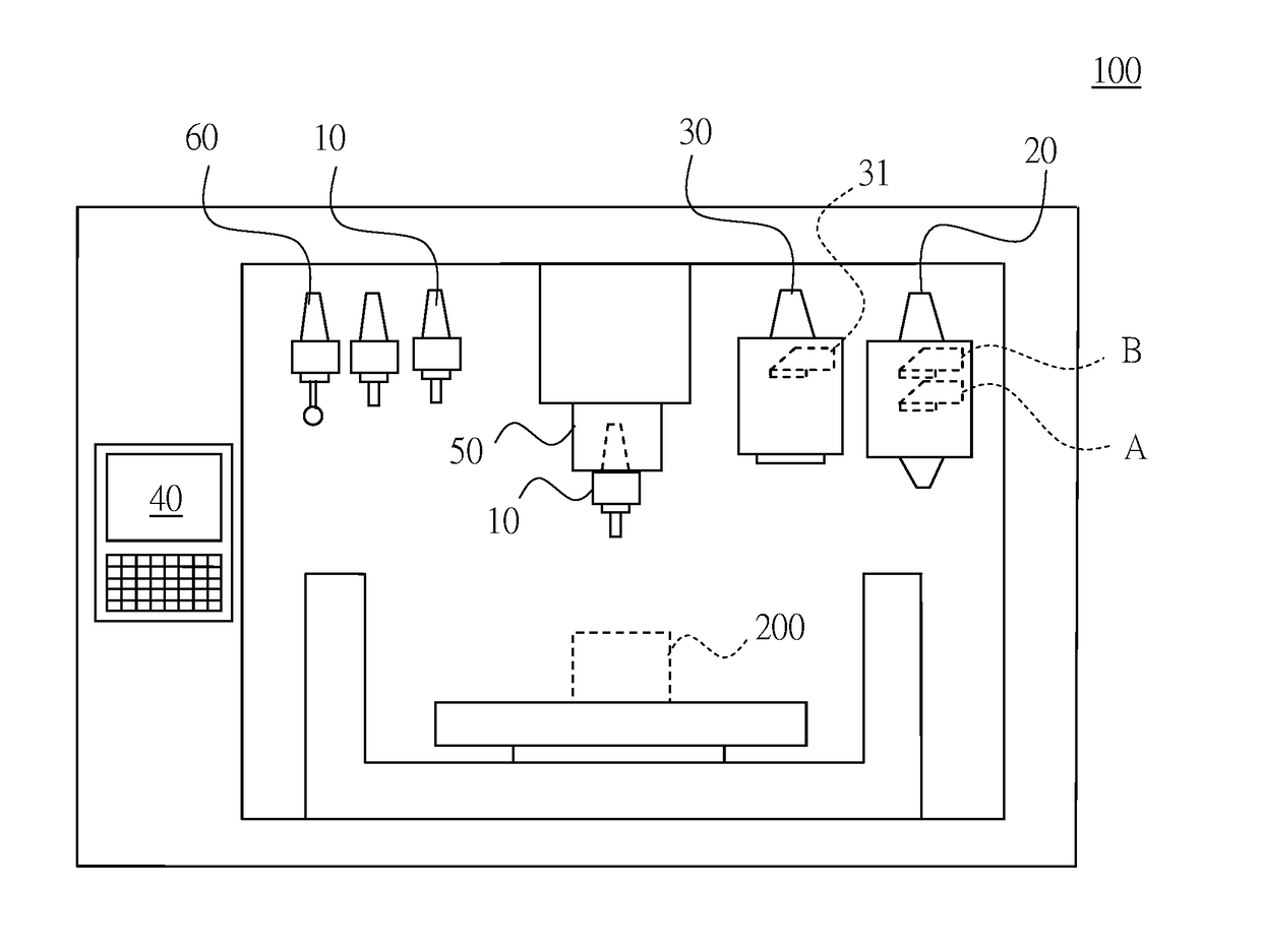
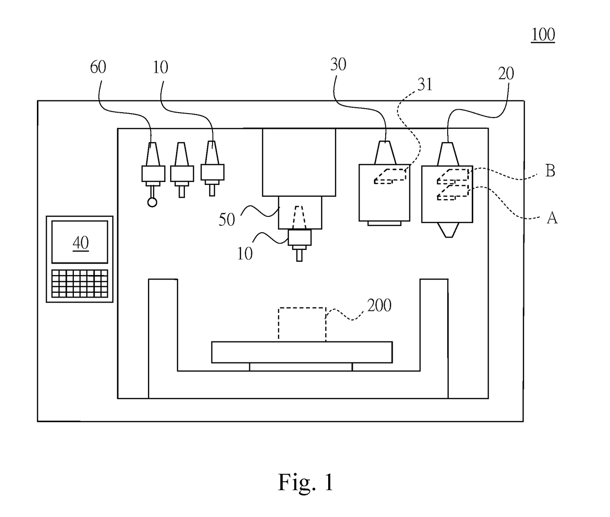
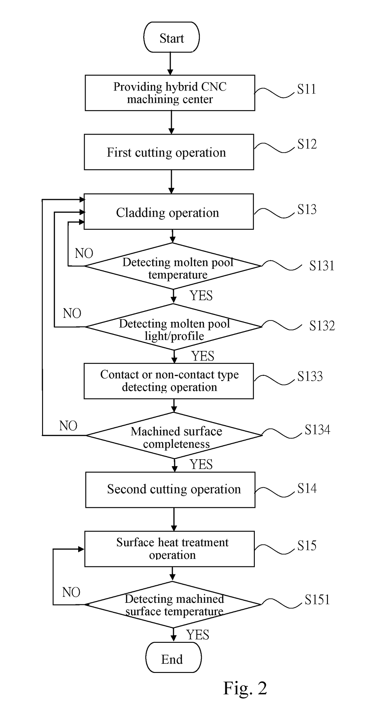
[0029]Refer now to FIGS. 1 and 2. A machining method of the hybrid CNC machining center according to the present invention comprises steps of:

[0030]S11: providing a hybrid CNC machining center 100 including at least a cutting tool head 10, a laser cladding tool head 20, a laser surface heat treatment tool head 30, and a computer numerical control unit 40, wherein the cutting tool head 10, the laser cladding tool head 20 and the laser surface heat treatment tool head 30 are alternately installed in a tool holder 50 of the hybrid CNC machining center 100;

[0031]S12: processing a first cutting operation, wherein the cutting tool head 10 is configured to cut at least a machined surface of a work-piece 200;

[0032]S13: processing a cladding operation, wherein the laser cladding tool head 20 is configured to clad the machined surface;

[0033]S14: processing a second cutting operation, wherein the cutting tool head 10 is configured to cut the cladded machined surface; and

[0034]S15: processing a...

third embodiment

[0045]Refer now to FIG. 5, which is a schematic structural view of a laser cladding tool head according to the present invention. In the above-mentioned embodiment of the present invention, the laser cladding tool head 20 further comprises: a shell body 21, a shank portion 22, and a laser module 23, wherein the shank portion 22 is disposed on a top of the shell body 21, and is detachably combined with a tool holder chuck 50 of the above-mentioned hybrid CNC machining center 100; and the laser module 23 includes a laser input portion 231, a laser output portion 232, and a spectroscopic assembly 233, wherein the laser input portion 231 is horizontally disposed on a side surface of the spectroscopic assembly 233, and the laser output portion 232 is perpendicularly disposed on a bottom surface of the spectroscopic assembly 233.

[0046]Refer now to FIG. 6, which is a schematic operating view of the laser cladding tool head according to the third embodiment of the present invention, and for...

second embodiment

[0055]In one possible embodiment of the present invention, the first sensing module 24 can be a temperature sensor module, and the second sensing module 25 can a camera sensor module. Probably, in another possible embodiment of the present invention, the first sensing module 24 can be a camera sensor module, and the second sensing module 25 can a temperature sensor module. Furthermore, the steps S32 and S33 can be changed their order, or to be executed alone. According to an actual requirement, users can flexibly adjust it, and apply it to the first and second embodiment of the present invention, not limited in the present invention.

[0056]As mentioned above, the present invention provides the laser cladding tool head and the machined surface sensing method thereof, by the laser cladding tool head simultaneously including a temperature sensing module and a camera sensing module, the laser cladding tool head can sense the temperature, lightness, and profile of a molten pool, and then ...


PUM

PropertyMeasurementUnit
Angleaaaaaaaaaa
Temperatureaaaaaaaaaa

Abstract

A laser cladding tool head and a machined surface sensing method thereof are provided for a computer numerical control (CNC) machining center. The laser cladding tool head has a temperature sensing module and a camera sensing module, which can sense the temperature, lightness, and profile of a molten pool, and then provide them to a computer numerical control unit for a feedback control, so as to increase the processing effect and quality of a work-piece.

Description

FIELD OF THE INVENTION[0001]The present invention relates to a laser cladding tool head and a machined surface sensing method thereof, and more particularly to a laser cladding tool head and a machined surface sensing method thereof with a temperature sensor and a camera.BACKGROUND OF THE INVENTION[0002]A traditional computer numerical control (CNC) machining center can process various cutting operations by changing different cutting tool heads, but only the cutting operations are processed. When a welding (repair welding) or heat treatment operation is necessary to be pressed therewith, it must use other machine tools, so that the steps and the process time of the machining operations are substantially increased.[0003]Especially, for a machining method using laser, such as a laser cladding operation, it must use special laser machine tools to work. Therefore, if the laser machine tool is necessary to be used in entire of the machining processes, a work-piece is moved, fixed, and ma...

Claims


Application Information

Patent Timeline
IPC IPC(8): B23K26/03B23K26/06B23K26/34G01N21/84
CPCB23K26/032B23K26/34G01N2021/8427B23K26/034B23K26/0626G01N21/84B23K26/0093C21D9/50G01N2021/8416
Inventor CHEN, HSINPAOKAO, HUAIENLIU, ZONGSHINTSAI, TSUNGHSIENCHEN, TINGCHANGYEN, JUIHSIUNG
Owner TONG-TAI MASCH & TOOL CO LTD
Why Eureka
Try Eureka