Separated compact buried box-type substation

A box-type substation, compact technology, applied in the direction of closed substation, substation, substation/switch layout details, etc., can solve the problem of inability to arrange, etc., achieve the effect of free and flexible combination installation, reduce floor space, and improve reliability

Pending Publication Date: 2020-12-18
基元电气有限公司
View PDF0 Cites 1 Cited by
  • Summary
  • Abstract
  • Description
  • Claims
  • Application Information

AI Technical Summary

Problems solved by technology

[0005] Aiming at the deficiencies of the prior art, the present invention provides a separate compact buried box-type substation, mainly to solve the problem that the above-ground part and the underground part of the integrated buried box-type substation need to be closely connected as a whole, which is affected by the surrounding environment. Conditional constraints may cause problems that cannot be arranged

Method used


Image

  • Separated compact buried box-type substation
  • Separated compact buried box-type substation
  • Separated compact buried box-type substation

Examples


Embodiment 1

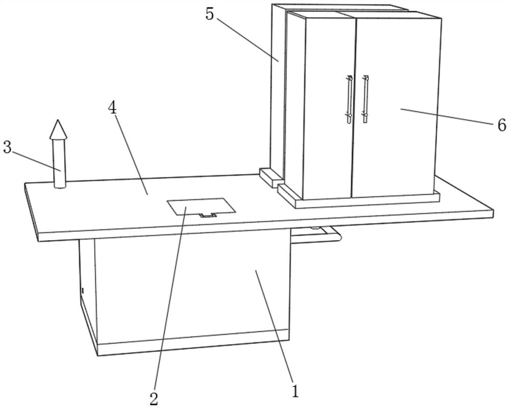
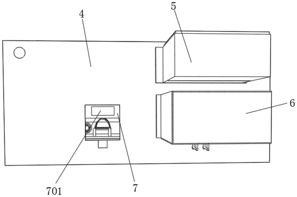
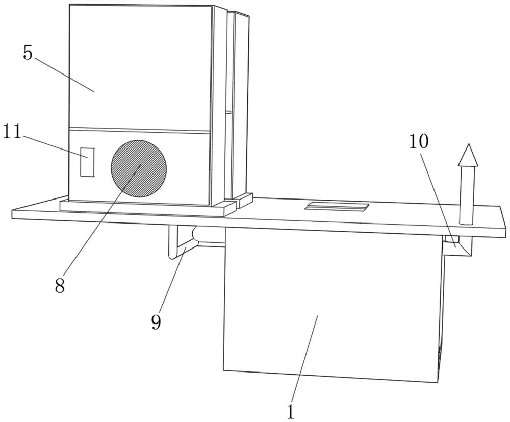
[0031] refer to Figure 1-5 , a separate compact underground box-type substation, including an underground box 1 installed under the ground 4, an underground chamber is dug under the ground 4, and then the underground box 1 is placed in the underground chamber, and the ground 4 A cooling box 5 and a low-voltage cabinet 6 are installed on the upper surface, and one side of the underground box 1 is provided with an outlet hole, and a waterproof chuck 27 is installed in the hole, and the waterproof chuck 27 improves the sealing performance of the underground box 1, and the waterproof chuck 27 An outlet pipe 17 is plugged into the inner seal, and the other end of the outlet pipe 17 is connected with the low-voltage cabinet 6. The inner wall of one side of the underground box 1 is fixed with a bridge frame 24 by bolts. The transformer 12 is installed in the underground box 1, and the top of the ground 4 is installed There is a ventilation column 3, and one side of the underground b...

Embodiment 2

[0035] refer to Figure 6 , a separate compact underground box-type substation, including a camera 28 fixed on the top inner wall of the underground box 1 by bolts, the camera 28 can monitor the operation status of the transformer 12 in real time, the top of the cooling box 5 and the low-voltage cabinet 6 The outer wall is respectively fixed with two supporting columns 29 by bolts, and the top of the supporting columns 29 is fixed with a rainproof shed 30 by bolts, and the rainproof shed 30 can prevent rainwater from corroding the cooling box 5 and the low-voltage cabinet 6.

[0036] The working principle of this embodiment: when in use, the staff can monitor the operating status of the transformer 12 in real time through the camera 28, and the rainproof shed 30 can prevent rainwater from falling on the cooling box 5 and the low-voltage cabinet 6 to protect them.

[0037] The electrical components appearing in this article are all connected with the external main controller an...


PUM


Abstract

The invention relates to the technical field of power supply and distribution of a power system, and discloses a separated compact buried box-type substation, which comprises an underground box installed under the ground, a ventilation column installed at the top of the ground, a heat dissipation box and a low-voltage cabinet installed on the upper surface of the ground, and a wire outlet hole formed in one side of the underground box, a waterproof chuck is installed in the wire outlet hole, a wire outlet pipe is arranged in the waterproof chuck, the other end of the wire outlet pipe is communicated with the low-voltage cabinet, a bridge frame is fixedly connected to the inner wall of one side of the underground box, a transformer is installed in the underground box, an air inlet hole is formed in one side of the underground box, and an air inlet pipe is arranged in the air inlet hole. The box-type substation can be split into three independent modules, namely the underground box, theheat dissipation box and the low-voltage cabinet, free and flexible combination and installation are realized, the limitation of a site is avoided, the high-voltage cabinet does not need to be configured on site, only the low-voltage cabinet and the ventilation column which occupy extremely small ground are left on the ground part, and the occupied area is reduced.

Description

technical field [0001] The invention relates to the technical field of power supply and distribution in electric power systems, in particular to a separate compact underground box-type substation. Background technique [0002] With the acceleration of urban and rural modernization, urban construction has entered the stage of urban beauty aimed at improving streetscapes and city appearances. Traditional box-type substations occupy a large area. In some crowded streets, pedestrian streets and other scenes, traditional box-type substations cannot be used to solve the problem of power expansion and cause serious inconvenience to the travel of nearby residents. The separated compact underground box-type substation is a new type of complete power equipment developed to meet the above scenarios. [0003] Box-type substations usually include transformers and power distribution units such as high and low-voltage cabinets that match the transformers. The current solution to the above...

Claims


Application Information

Patent Timeline
Patent Type & Authority Applications(China)
IPC IPC(8): H02B1/56H02B1/28H02B7/08
CPCH02B1/28H02B1/565H02B7/08
Inventor 刘文
Owner 基元电气有限公司
Why Eureka
Try Eureka