PWM signal generator circuit

A PWM signal and generator technology, applied in the direction of instruments, electrical components, adjusting electrical variables, etc., can solve the problems of large duty cycle, increase the complexity of the system, blow up the machine, etc., to reduce the PCBA area, save peripheral circuits, The effect of saving program cost

Pending Publication Date: 2020-12-18
福州耀天芯电子有限公司
View PDF0 Cites 0 Cited by
  • Summary
  • Abstract
  • Description
  • Claims
  • Application Information

AI Technical Summary

Problems solved by technology

[0003] Existing technologies are generally processed during signal transmission or reception; these technologies will increase the complexity of the system in practical applications, which is not conducive to the mainstream trend of product miniaturization and higher cost performance; in traditional design schemes, comes out often Image 6 In the situation shown, that is, during the system startup process and power-off process, there will be a phenomenon that the duty cycle is greater than 45%, which will cause components such as MOS tubes and inductors to be burned due to overcurrent. Therefore, the traditional solution is used in actual product applications. There may be greater risks, especially in high-pressure systems, which are prone to bombing

Method used


Image

  • PWM signal generator circuit
  • PWM signal generator circuit
  • PWM signal generator circuit

Examples


Embodiment 1

[0032] Please refer to Figure 1 to Figure 5 , Embodiment 1 of the present invention is:

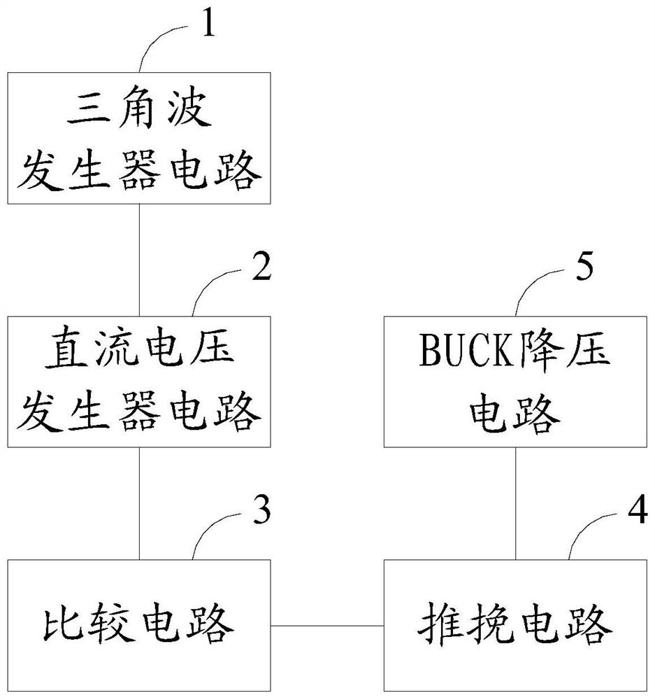
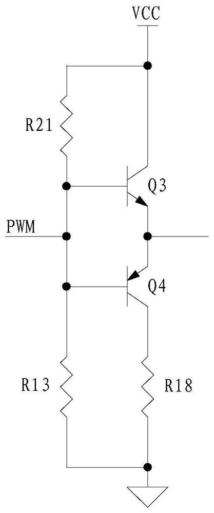
[0033] Please refer to figure 1 , a PWM signal generator circuit, comprising a triangle wave generator circuit 1, a DC voltage generator circuit 2 and a comparison circuit 3, the DC voltage generator circuit 2 is electrically connected to the triangle wave generator circuit 1 and the comparison circuit 3 respectively, the The comparison circuit 3 is electrically connected to the push-pull circuit 4 of the peripheral, and the push-pull circuit 4 is electrically connected to the BUCK step-down circuit 5 of the peripheral.

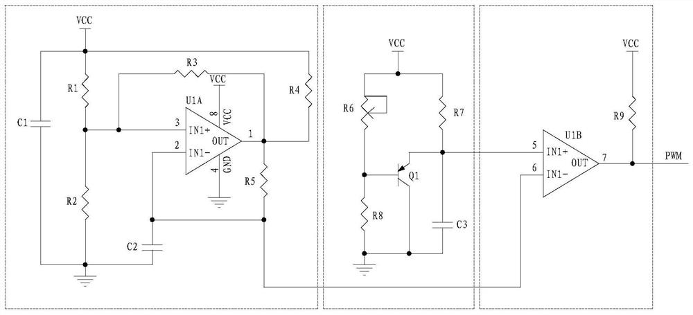
[0034] Please refer to figure 2 , the triangular wave generator circuit 1 includes resistor R1 (resistance value is 9.1kΩ), resistor R2 (resistance value is 9.1kΩ), resistor R3 (resistance value is 9.1kΩ), resistor R4 (resistance value is 9.1kΩ), resistor R5 (resistance value is 9.1kΩ), capacitor C1 (capacitance value is 0.1μF, voltage value is 50V), capacitor C2 (...


PUM


Abstract

The invention relates to the technical field of PWM signal generator circuits, in particular to a PWM signal generator circuit which comprises a triangular wave generator circuit, a direct-current voltage generator circuit and a comparison circuit, wherein the direct-current voltage generator circuit is electrically connected with the triangular wave generator circuit and the comparison circuit, and the comparison circuit is electrically connected with an external push-pull circuit. The push-pull circuit is electrically connected with an external BUCK step-down circuit. A PWM signal is generated through arranging the triangular wave signal generator circuit and the direct-current voltage generator circuit and through the comparison circuit for controlling the switch tube, and therefore theduty ratio of the system is slowly increased in the starting process of the system. In the power-down process of the system, the output duty ratio is slowly decreased; in the whole process from system startup and normal work to system power failure, the output duty ratio is not higher than 45%, so that the safety and reliability of the system are fundamentally ensured.

Description

technical field [0001] The invention relates to the technical field of PWM signal generator circuits, in particular to a PWM signal generator circuit. Background technique [0002] Nowadays, with the rapid development of the electronic industry, electronic products are developing towards miniaturization, convenience and high reliability; to meet these application requirements, the power conversion part involved in the product needs to have higher and higher switching frequencies, As we know, with the increase of the switching frequency, the size of the power inductor or transformer can be greatly reduced, so as to meet the needs of product miniaturization; however, with the increase of the switching frequency, problems such as EMI and output overshoot are also Then, in order to solve the EMI problem, the method of increasing shielding or isolation and dredging is generally adopted. In order to solve the problem of output overshoot, the feedback system of the system needs to ...

Claims


Application Information

Patent Timeline
Patent Type & Authority Applications(China)
IPC IPC(8): H02M1/36H02M3/156H03K7/08
CPCH02M1/36H02M3/156H03K7/08
Inventor 何铭森朱宇耀周金穗王宗彪
Owner 福州耀天芯电子有限公司
Why Eureka
Try Eureka