
Method for gassing bioreactors and gassing system

A bioreactor and gas supply system technology, applied in specific-purpose bioreactors/fermenters, methods for supporting/fixing microorganisms, bioreactor/fermenter combinations, etc., to achieve the effect of saving space

Pending Publication Date: 2020-12-18
ADOLF KUHNER
View PDF1 Cites 0 Cited by
  • Summary
  • Abstract
  • Description
  • Claims
  • Application Information

AI Technical Summary

Problems solved by technology

Gas mixing modules from Eppendorf require the use of valves and complex control electronics

Method used


Image

  • Method for gassing bioreactors and gassing system
  • Method for gassing bioreactors and gassing system
  • Method for gassing bioreactors and gassing system

Examples


Embodiment Construction

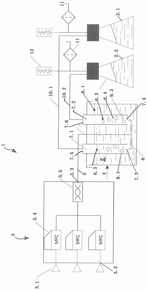
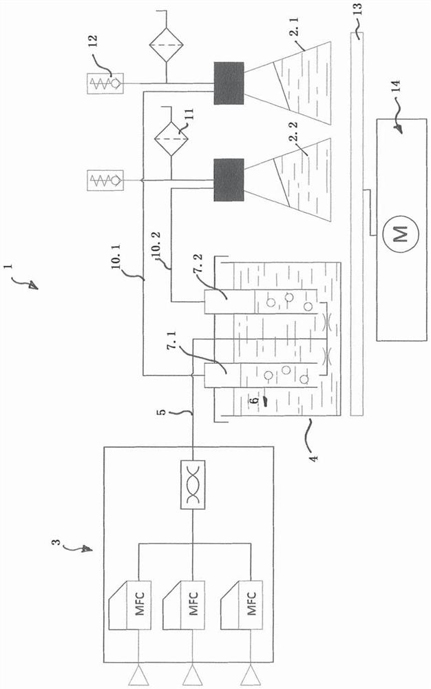
[0041] figure 1 A schematic diagram of a gas supply system (1 ) for supplying gas to a plurality of bioreactors (2.1, 2.2) is shown. In the examples, only two bioreactors are shown for reasons of clarity. However, with the gas supply system according to the invention, more than two, for example six, bioreactors can be gassed simultaneously without difficulty. The bioreactors (2.1, 2.2) are designed to accommodate biomass, liquid culture medium and to introduce a gas supply.

[0042] As another important part, the gas supply system (1) includes a gas supply device (3) and a container (4) for providing a constant air flow, the air flow contains a mixture of three gases in the embodiment, the container is set to humidify the airflow and divide it into partial airflows.

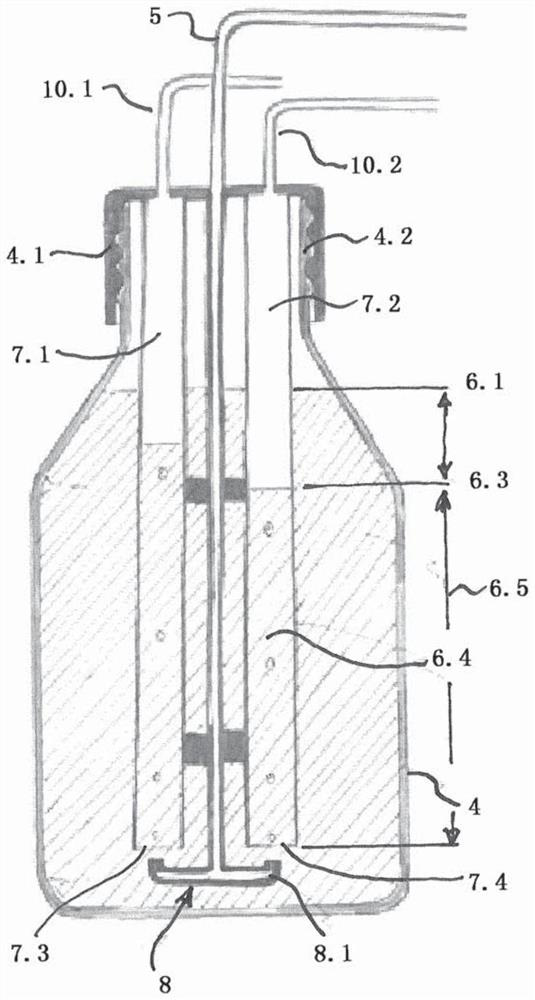
[0043] The container (4) contains a liquid fill (6) into which the ascending lines (7.1, 7.2) are immersed perpendicularly to the liquid level (6.1). The ascending lines (7.1, 7.2) are implemented as tubes fo...


PUM


Abstract

To create a method for gassing a plurality of bioreactors and to create a gassing system, which, without a separate humidifying device, divides with high distribution precision a constant gas flow into a plurality of partial gas flows having a predefined volume flow, which can be kept constant at the predefined level even when a counter-pressure in the gas line to the bioreactor fluctuates duringgassing, according to the invention, the gas distribution is uncoupled from the counter-pressure by means of a hydrostatic pressure equalisation, wherein the gas distribution brings about a necessaryhumidification of the gas flow at the same time.

Description

technical field [0001] The invention relates to a method for supplying a plurality of bioreactors with gas, and a gas supply system for carrying out the method. Background technique [0002] A controlled gas supply with different gases or gas mixtures is required especially for the automatic detection of process parameters of microbial, biochemical, enzymatic and chemical reactions in reaction liquids in bioreactors which can Shake continuously until the reaction in all microreactors is complete. As a parameter of the reaction liquid, such as detecting oxygen conversion rate (OTR) and carbon dioxide conversion rate (CTR), and deriving parameters respiratory quotient (RQ) and maximum specific growth rate (μ max ). [0003] Universal measuring systems are known from the prior art for optimizing biological processes in shake flasks by knowing the previously mentioned process parameters (cf. Hitec-Zang, Bioprozessoptimierungin Schüttelkolben (Optimization of biological process...

Claims


Application Information

Patent Timeline
IPC IPC(8): C12M1/00C12M1/12C12M3/06
CPCC12M23/40C12M23/58C12M25/10C12M27/16C12M23/22C12M29/04C12M29/20
Inventor 蒂博尔·安德莱西蒙·保罗·聚姆布伦嫩曼弗雷德·沙尔安德烈亚斯·里希特
Owner ADOLF KUHNER
Learn More