Impact ionisation spray or electrospray ionisation ion source

A technology of electrospray ionization and ion source, which is applied in the field of ion mobility spectrometer and mass spectrometer, and can solve the problems of not using it

Pending Publication Date: 2020-12-18
MICROMASS UK LTD
View PDF0 Cites 1 Cited by
  • Summary
  • Abstract
  • Description
  • Claims
  • Application Information

AI Technical Summary

Problems solved by technology

However, such nebulizers are non-conductive and therefore not used ...

Method used


Image

  • Impact ionisation spray or electrospray ionisation ion source
  • Impact ionisation spray or electrospray ionisation ion source
  • Impact ionisation spray or electrospray ionisation ion source

Examples


Embodiment Construction

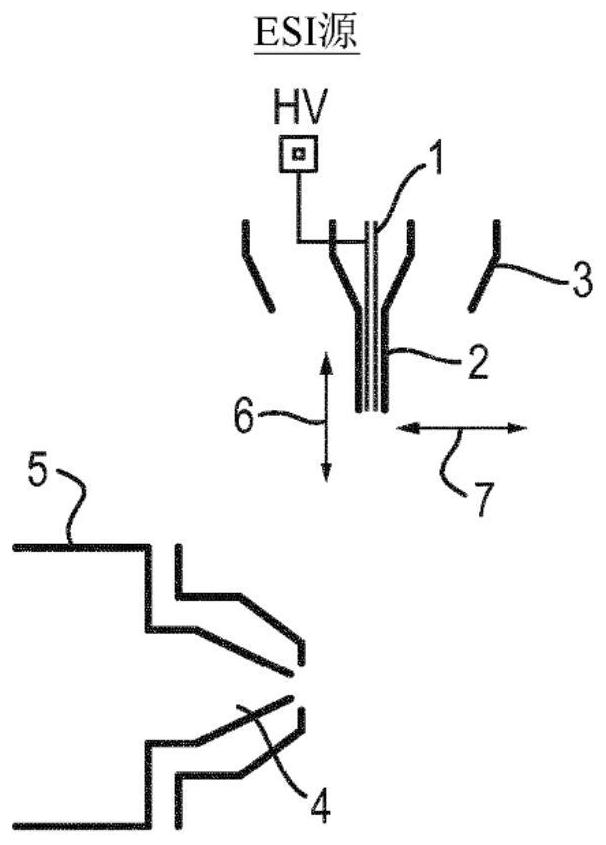
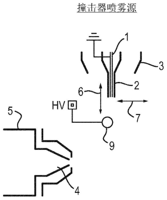
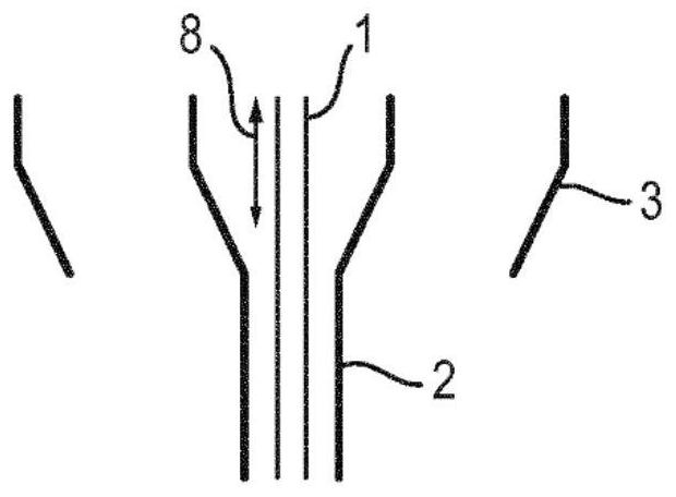
[0082] Figures 1A-1C illustrate typical electrospray ionization ion sources and impactor spray ionization ion sources for use in liquid chromatography / mass spectrometry (LC / MS) systems.

[0083] Figure 1 shows a typical electrospray ionization ion source. In the electrospray ionization ion source of FIG. 1 , the nebulizer is constructed by an inner liquid conduit 1 and an outer atomizing gas conduit 2 . Both conduits are constructed of stainless steel. In this example, the liquid conduit 1 has an inner diameter of 130 μm and an outer diameter of 230 μm. In this example, the inner diameter of the gas conduit 2 is 330 μm.

[0084] In operation, liquid flows into the liquid conduit 1 at a rate typically in the range of 10 μL / min to 2 mL / min. Gas line 2 was pressurized to 100 psi with nitrogen to generate a high velocity nebulizer gas flow of typically 200 L / hr. To heat the charged droplets of the nebulized sample, a second flow of nitrogen gas (1000 L / min) was passed between ...


PUM


Abstract

An impact ionisation spray or electrospray ionisation ion source comprising a nebuliser (30) having a first conduit (11) for providing a liquid sample and a second conduit (10) for providing a nebulisation gas in order to nebulise the liquid sample is disclosed. The first conduit (11) and second conduit (10) are of unitary construction with each other and may be made from glass. The ion source canprovide a consistent and/or predictable spray profile for the nebulised sample.

Description

[0001] Cross References to Related Applications [0002] This application claims priority to and benefit from UK Patent Application No. 1807914.5, filed 16 May 2018. The entire content of this application is incorporated herein by reference. technical field [0003] The present invention relates generally to impactor spray (or impact ionization) ion sources or electrospray ionization ion sources, and to mass spectrometers and / or ion mobility spectrometers comprising impactor spray ionization sources or electrospray ionization ion sources. Background technique [0004] Impactor spray (or impact ionization) ion sources and electrospray ionization (ESI) ion sources can be used, for example, in liquid chromatography / mass spectrometry (LC / MS) systems. Both types of ion sources typically utilize a pneumatic nebulizer to convert the liquid stream from a liquid chromatography (LC) column into a charged aerosol. This process typically takes place in an atmospheric or near-atmospher...

Claims


Application Information

Patent Timeline
IPC IPC(8): H01J49/04H01J49/16
CPCH01J49/045H01J49/167G01N30/7266G01N27/622H01J49/14
Inventor 斯特万·巴伊奇
Owner MICROMASS UK LTD
Why Eureka
Try Eureka