Manufacturing process of shell with optical heart rate inductive sensor and shell

A technology of inductive sensor and manufacturing process, applied in applications, other home appliances, home appliances, etc., can solve the problems of increasing living costs, single shell structure, rarely having a barrier function, etc., to achieve the effect of saving living expenses

Active Publication Date: 2020-12-22
深圳市亿铭粤科技有限公司
View PDF4 Cites 0 Cited by
  • Summary
  • Abstract
  • Description
  • Claims
  • Application Information

AI Technical Summary

Problems solved by technology

[0002] The shell is an indispensable part of electronic products. At present, the shells used in electronic products made of existing technology have a single structure and a single function. The electronic components are enclosed in a closed space, which has a barrier effect and rarely has a barrier removal function. Functions other than the function, such as the heart rate sensing function, which is a technology that uses light to measure the pulse. The optical heart rate sensing sensor detects the amount of blood circulating in the wrist at a specific time; Optical heart rate sensing sensors, such as built-in optical heart rate sensing sensors on bracelets or watches, for people who need this, they need to purchase wearable devices such as smart bracelets and smart watches separately, which will increase the living cost of such people; and At the same time, most people are not used to wearing watches, bracelets and other devices at present, so they tend to forget to wear them when going out, and wearing such wearable devices means that they need to carry more items, which brings a lot of inconvenience to users

Method used


Image

  • Manufacturing process of shell with optical heart rate inductive sensor and shell
  • Manufacturing process of shell with optical heart rate inductive sensor and shell
  • Manufacturing process of shell with optical heart rate inductive sensor and shell

Examples


Embodiment 1

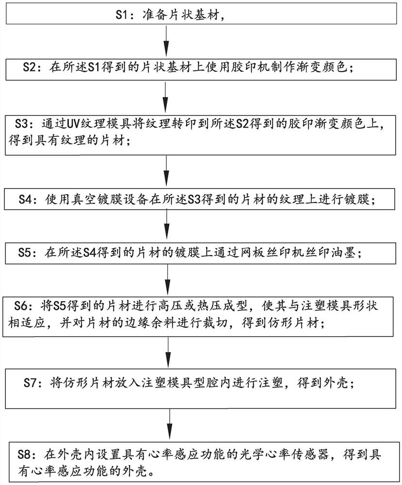
[0028] This embodiment provides a manufacturing process for a housing with an optical heart rate sensing sensor, such as figure 1 shown, including the following steps:

[0029] S1, preparing a sheet substrate; the substrate is made of a mixture of PMMA+PC; PMMA refers to polymethyl methacrylate, and PC refers to polycarbonate.

[0030] S2, using an offset printing machine to make gradient colors on the sheet substrate obtained in S1; the specific process is, step a, using the existing process to make a CTP plate, and output full-page or partial dots; step b, for printing ink Adjust the ratio and add additives in proportion. The additive is varnish, accounting for 20%-60%. With the help of the two laws of oil-water immiscibility and selective adsorption of the printing plate, the ink and water are on the printing plate Keep mutual balance to realize dot transfer, and thus achieve the effect of brightening and anti-reflection of printed images.

[0031] S3, transfer the textur...

Embodiment 2

[0041] Compared with Example 1, S1, S2, S4, S7, S8 are completely consistent, the difference is:

[0042] S3, transfer the texture to the offset gradient color obtained in S2 through the UV texture mold to obtain a textured sheet; the specific process is to pour the UV glue on the textured mold, put the material, and use a roller The press uniformly coats a layer of UV glue on the entire surface of the UV texture, and uses an LED light with a main spectrum of 350nm for exposure. After 3 seconds of exposure and curing, the material is torn off, and the UV glue texture is transferred to the sheet.

[0043] In this step, the material is polyethylene terephthalate (PET). Texture rendering material is UV glue (acrylate).

[0044] S5, on the coated film of the sheet material obtained in said S4, use a screen printing machine to screen ink; the specific process is to use a 300 mesh screen to carry out ink screen printing on the coated surface, and each screen printing needs to be bake...

Embodiment 3

[0048] Compared with Example 1, S1, S2, S4, S7, S8 are completely consistent, the difference is:

[0049] S3, transfer the texture to the offset gradient color obtained in S2 through the UV texture mold to obtain a textured sheet; the specific process is to pour the UV glue on the textured mold, put the material, and use a roller The press uniformly coats a layer of UV glue on the entire surface of the UV texture, and uses an LED light with a main spectrum of 350nm for exposure. After 5 seconds of exposure and curing, the material is torn off, and the UV glue texture is transferred to the sheet.

[0050] In this step, the material is polymethyl methacrylate (PMMA). Texture rendering material is UV glue (acrylate).

[0051] S5, on the coated film of the sheet material obtained in said S4, use a screen printing machine to screen ink; the specific process is to use a 600-mesh screen to carry out ink screen printing on the coated surface, and each screen printing needs to be bake...


PUM


Abstract

The invention belongs to the technical field of shell processing, and discloses a manufacturing process of a shell with an optical heart rate inductive sensor. The manufacturing process comprises thefollowing steps that S1, a sheet-shaped base material is prepared; S2, gradient colors are manufactured on the sheet-shaped base material by using an offset printing press; S3, texture is transferredto the offset printed gradient colors through a UV texture mold; S4, coating is carried out on the texture of the sheet by using vacuum coating equipment; S5, ink screen printing is carried out on a coated film of the sheet through a screen printing machine; S6, the sheet is subjected to high-pressure or hot-press molding, and a profiling sheet is obtained; S7, the profiling sheet is put into an injection mold cavity for injection molding, and the shell is obtained; and S8, the optical heart rate inductive sensor with a heart rate induction function is arranged in the shell, and the shell withthe heart rate induction function is obtained. For the crowd with the demand, independent purchase of wearable equipment is not needed, so that the living expenditure is saved; and when a user goes out, a mobile phone is a necessity and is generally rarely forgotten to be carried, and meanwhile, the wearable equipment except the mobile phone does not need to be carried, so that no extra inconvenience is added to the user.

Description

technical field [0001] The invention relates to a manufacturing method of an electronic product casing, in particular to a manufacturing process of a casing equipped with an optical heart rate sensing sensor, thereby having a heart rate sensing function, and the casing manufactured by the process. Background technique [0002] The shell is an indispensable part of electronic products. At present, the shells used in electronic products made of existing technology have a single structure and a single function. The electronic components are enclosed in a closed space, which has a barrier effect and rarely has a barrier removal function. Functions other than the function, such as the heart rate sensing function, which is a technology that uses light to measure the pulse. The optical heart rate sensing sensor detects the amount of blood circulating in the wrist at a specific time; Optical heart rate sensing sensors, such as built-in optical heart rate sensing sensors on bracelets...

Claims


Application Information

Patent Timeline
Patent Type & Authority Applications(China)
IPC IPC(8): B29D99/00
CPCB29D99/006
Inventor 曹祖铭
Owner 深圳市亿铭粤科技有限公司
Why Eureka
Try Eureka