Combined partial circulation biomass gasification furnace and working method thereof

A biomass and combined technology, applied in the petroleum industry, the manufacture of combustible gas, etc., can solve the problems affecting the germination and rooting of new crops, restricting biomass gasification technology, and reducing the efficiency of biomass gasification, etc., to achieve simple biomass Step-by-step gasification to achieve drying and high utilization

Active Publication Date: 2020-12-22
XI AN JIAOTONG UNIV
View PDF9 Cites 0 Cited by
  • Summary
  • Abstract
  • Description
  • Claims
  • Application Information

AI Technical Summary

Problems solved by technology

However, tar is inevitably produced in the process of biomass gasification, which leads to the reduction of biomass gasification efficiency. At the same time, tar will also block and corrode pipelines. At this stage, there is a lack of effective tar treatment methods, which limits the better development of biomass gasification technology.
[0003] At the same time, the distribution of townships and rural areas in my country is relatively scattered, and the amount of straw and other wastes produced by farming is relatively large. Direct burning will cause serious environmental pollution problems. Therefore, a large amo

Method used


Image

  • Combined partial circulation biomass gasification furnace and working method thereof
  • Combined partial circulation biomass gasification furnace and working method thereof

Examples


Embodiment Construction

[0032] The present invention will be described in further detail below in conjunction with accompanying drawing, and its content is explanation of the present invention rather than limitation:

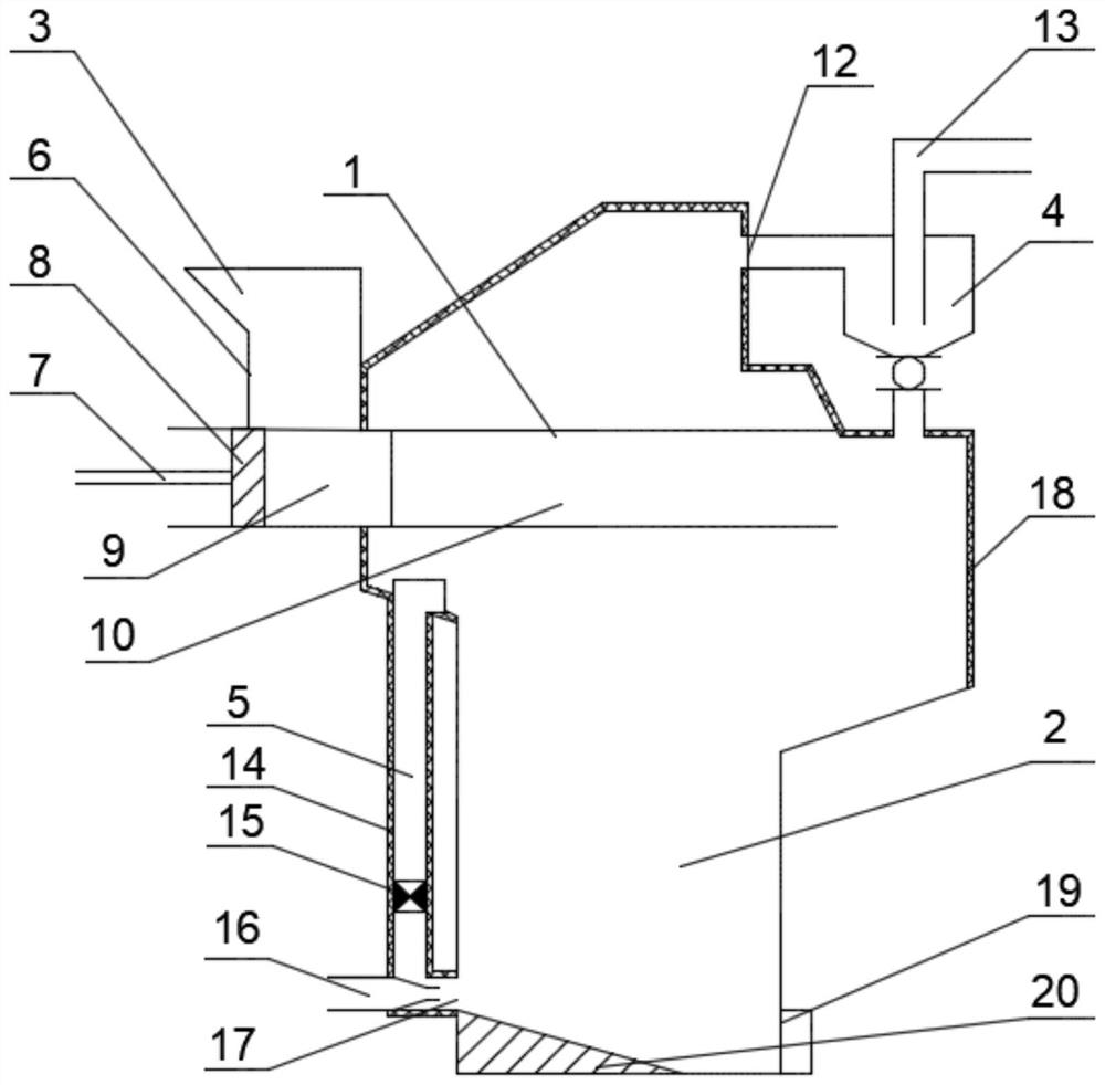
[0033] Such as figure 1 , is a combined partial circulation biomass gasifier of the present invention, including a horizontal furnace body 1, a vertical furnace body 2, a feeding system 3, a dust removal device 4 and a gasification gas circulation device 5.

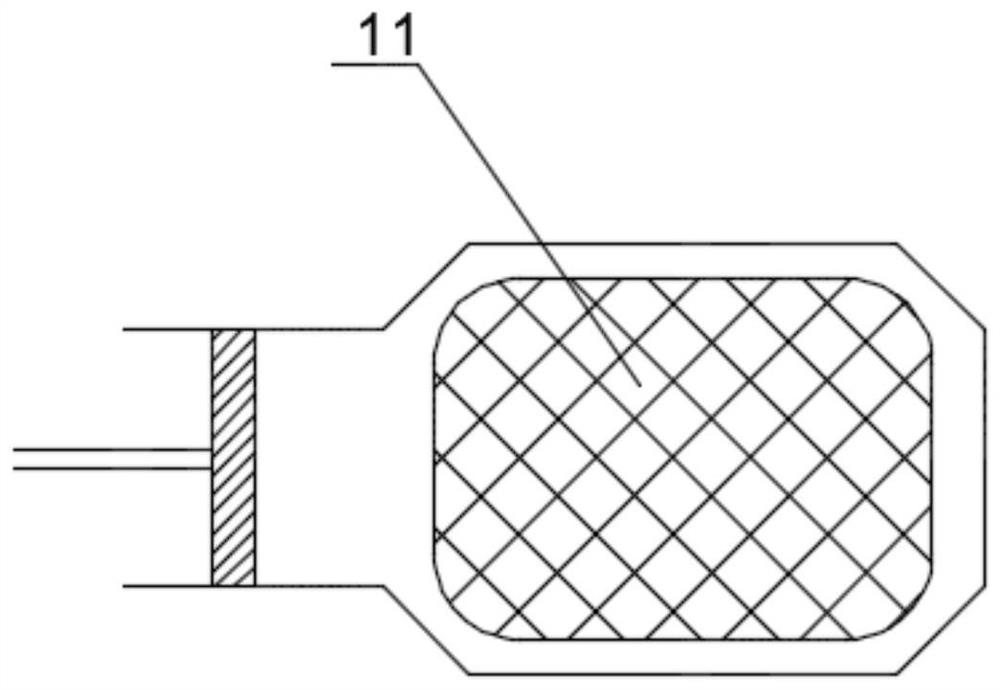
[0034] The feeding system 3 includes a feeding hopper 6, a hydraulic feeding device 7 and a feeding plate 8, the feeding hopper 6 is arranged above the feeding section 9, and the hydraulic feeding device 7 and the feeding plate 8 are arranged in the feeding section 9 , The hydraulic feeding device 7 is connected with the feeding plate 8 .

[0035] The horizontal furnace body 1 comprises a feeding section 9 and a drying-gasification section 10, the length of the feeding section 9 is 1 / 3 of the horizontal furnace body 1, and the le...


PUM


Abstract

The invention discloses a combined partial circulation biomass gasification furnace and a working method thereof, belonging to the technical field of biomass energy gasification and utilization. The feeding section of a horizontal furnace body is respectively connected with a feeding system and a drying and gasifying section; the drying and gasifying section is embedded into the inner middle upperpart of a vertical furnace body and is separated from the vertical furnace body through an upper partition plate and a lower partition plate respectively; an outlet of the drying and gasifying section communicates with the middle part of the vertical furnace body; vent holes are formed in the upper partition plate and the lower partition plate; a crude gas outlet is formed in the upper portion ofthe vertical furnace body and connected with a dust removal device; the dust removal device is connected with a combustible gas outlet pipe, and a solid outlet of the dust removal device communicateswith the middle part of the vertical furnace body; an air inlet is formed in one side of the bottom of the vertical furnace body, and an ash outlet is formed in the other side of the bottom of the vertical furnace body; a gasified gas circulating device is arranged outside the vertical furnace body; and an upper end inlet of the gasified gas circulating device communicates with the middle part ofthe vertical furnace body, and a lower end inlet of the vertical furnace body communicates with the air inlet. According to the invention, gasification efficiency can be improved, and meanwhile, a tar content in generated combustible gas is greatly reduced.

Description

technical field [0001] The invention belongs to the technical field of gasification and utilization of biomass energy, and in particular relates to a combined partial circulation biomass gasification furnace and a working method thereof. Background technique [0002] With the rapid development of my country's economy, the demand for new clean energy continues to increase. Biomass energy, as a low-carbon emission and sustainable Difficulties and other disadvantages. Biomass gasification technology can convert low-grade biomass energy into high-quality gas fuel, which can replace fossil fuels such as natural gas and be used in residential gas, heating, gas power generation and other fields, so it has been widely used. However, tar is inevitably produced in the process of biomass gasification, which leads to the reduction of biomass gasification efficiency. At the same time, tar will also block and corrode pipelines. At this stage, there is a lack of effective tar treatment met...

Claims


Application Information

Patent Timeline
IPC IPC(8): C10J3/20C10J3/72C10J3/84
CPCC10J3/20C10J3/721C10J3/84
Inventor 杨富鑫赵旭谭厚章
Owner XI AN JIAOTONG UNIV
Why Eureka
Try Eureka