Prefabricated reinforcement cage rapid butt joint device and construction method thereof

A technology of docking device and reinforcement cage, which is applied in basic structure engineering, processing of building materials, sheet pile walls, etc., can solve the problem of slow construction progress of straight thread sleeve connection of reinforcement cages, reducing the overall construction progress of reinforcement cage docking, and time-consuming Manpower and other issues to achieve the effect of improving construction efficiency, convenient movement, and improving efficiency

Active Publication Date: 2020-12-22
昆山市城乡建设有限公司
View PDF4 Cites 2 Cited by
  • Summary
  • Abstract
  • Description
  • Claims
  • Application Information

AI Technical Summary

Problems solved by technology

[0006] However, this construction method is very time-consuming and manpower-consuming. During normal construction, 2-3 construction workers are required to perform tightening operations, and the time spent on the entire tightening process accounts for more than 70% of the entire reinforcement cage installation time, which greatly reduces The overall construction progress of multi-section steel cage butt joint
[0007] In view of the related technologies mentioned above, based on the above analysis, the inventor believes that the construction progress of the steel cage straight thread sleeve connection before improvement is relatively slow, and the construction quality is average

Method used


Image

  • Prefabricated reinforcement cage rapid butt joint device and construction method thereof
  • Prefabricated reinforcement cage rapid butt joint device and construction method thereof
  • Prefabricated reinforcement cage rapid butt joint device and construction method thereof

Examples


Embodiment Construction

[0046] The following is attached Figure 1-4 The application is described in further detail.

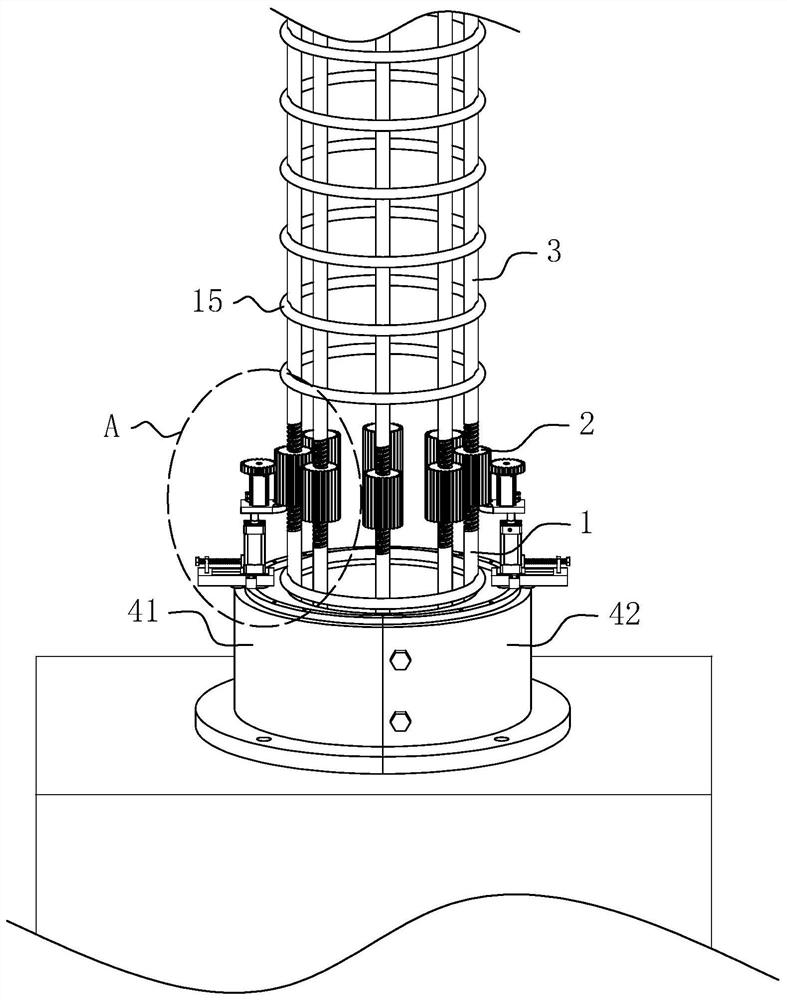
[0047] The embodiment of the present application discloses a quick docking device for prefabricated reinforcement cages. refer to figure 1 , the docking device includes a lower reinforcement cage arranged in the deep pit, the lower reinforcement cage is composed of a plurality of vertically arranged lower main reinforcements 1 and annular stirrups 15 sleeved outside the plurality of main reinforcements; The threaded sleeve 2 on the top of the lower main rib 1, the threaded sleeve 2 is set as the positive and negative wire straight threaded sleeve 2; it also includes a plurality of upper main ribs 3 arranged vertically, and the outer side walls of the upper main ribs 3 are also welded at intervals. Ring stirrup 15.

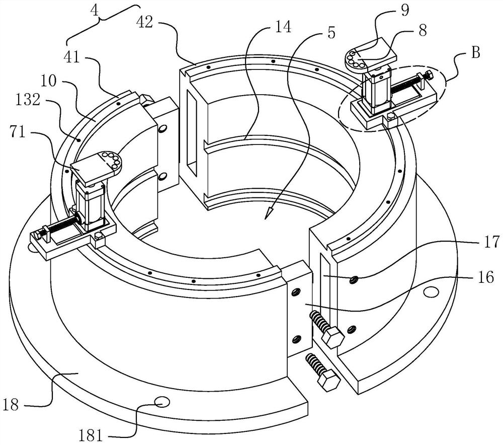
[0048] refer to figure 1 and figure 2 , also includes the limit card seat 4 that is used to define the lower reinforcement cage, the limit card seat 4 includes the ...


PUM


Abstract

The invention relates to a prefabricated reinforcement cage rapid butt joint device. The device comprises a plurality of vertically-arranged lower main reinforcements, threaded sleeves arranged at thetop ends of the lower main reinforcements and vertically-arranged upper main reinforcements, and further comprises a limiting clamping base which comprises a left clamping base and a right clamping base which are symmetrically arranged. Limiting cavities used for limiting the position of a lower reinforcement cage are formed in the left clamping base and the right clamping base correspondingly, the left clamping base and the right clamping base are detachably connected, and screwing assemblies used for automatically screwing the threaded sleeves are arranged on the upper surface of the limiting clamping base. Each screwing assembly comprises a driving motor vertically arranged on the upper surface of the limiting clamping base, a driving gear fixedly arranged on an output shaft of the driving motor and a driven gear ring arranged on the circumferential side wall of the corresponding threaded sleeve, the driving gears are meshed with the driven gear rings, and the driving motors are detachably connected to the upper surface of the limiting clamping base. The device has the effect of improving the butt joint construction efficiency of a reinforcement cage to a great extent.

Description

technical field [0001] The present application relates to the technical field of building construction components, in particular to a prefabricated reinforcement cage quick docking device and a construction method thereof. Background technique [0002] With the rapid development of China's infrastructure, steel cages, as an important part of building construction components, have been widely used. Generally, during the construction of bridges, culverts or high-rise buildings, ground foundations are required to be piled. Specifically, machine punching or water milling is used to drill deep holes. When the hole depth meets the design requirements, the reinforcement cage is lowered into the deep hole, and finally concrete is poured. [0003] For some ultra-long pile holes, it is necessary to match the ultra-long steel cage model. When the length of the steel cage is long (generally greater than 30 meters), it needs to be made in sections. The reason is that the transportation o...

Claims


Application Information

Patent Timeline
Patent Type & Authority Applications(China)
IPC IPC(8): E02D5/34E04C5/16E04G21/12
CPCE02D5/34E04C5/165E04G21/122
Inventor 陈卫根徐建明胡瑞邵明峦唐文祝
Owner 昆山市城乡建设有限公司
Why Eureka
Try Eureka